EasyManuals Logo
Home>Rockwell Automation>Servo Drives>Allen-Bradley Kinetix 6000

Rockwell Automation Allen-Bradley Kinetix 6000 User Manual

Rockwell Automation Allen-Bradley Kinetix 6000
268 pages
To Next Page IconTo Next Page
To Previous Page IconTo Previous Page
Page #59 background imageLoading...
Page #59 background image
Publication 2094-UM001A-EN-P — September 2006
Kinetix 6000 Connector Data 59
IAM and AM Motor Power and Brake Connector Pinouts
Motor Power Connector
Motor Brake/Resistive Brake Connector
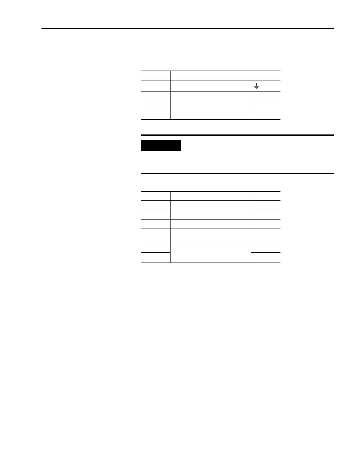
MP Pin Description Signal
4 Chassis ground
3
Three-phase motor power
W
2V
1U
IMPORTANT
To meet CE requirements, combined motor power cable length
for all axes on the same dc bus must not exceed 240 m (787 ft)
with 460V systems or 160 m (525 ft) with 230V systems.
Drive-to-motor power cables must not exceed 90 m (295.5 ft).
BC Pin Description Signal
6
Motor brake connections
MBRK-
5 MBRK+
4 Motor brake common COM
3
+24V brake input power (from LIM or
customer supplied)
PWR
2 Resistive brake module (RBM)
connections (from RBM and safety
string)
DBRK-
1 DBRK+

Table of Contents

Other manuals for Rockwell Automation Allen-Bradley Kinetix 6000

Questions and Answers:

Question and Answer IconNeed help?

Do you have a question about the Rockwell Automation Allen-Bradley Kinetix 6000 and is the answer not in the manual?

Rockwell Automation Allen-Bradley Kinetix 6000 Specifications

General IconGeneral
BrandRockwell Automation
ModelAllen-Bradley Kinetix 6000
CategoryServo Drives
LanguageEnglish

Related product manuals