Publication 2094-UM001A-EN-P — September 2006
166 Removing and Replacing the Kinetix 6000 Drive Modules
7. Re-apply power to the system.
8. Verify that the system is operating properly.
Removing the Power Rail
This procedure assumes you have removed all modules from the
power rail.
Follow these steps to remove the power rail.
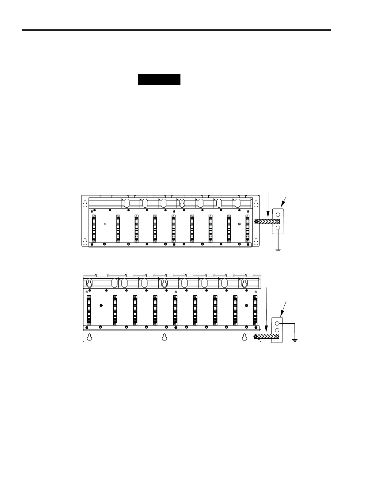
1. Disconnect the braided grounding strap from the grounding stud
located on the right side of the power rail.
2. Loosen the mounting bolts (removing the bolts is not necessary).
3. Lift the power rail up and off of the mounting bolts.
TIP
Because IAM and AM parameters reside in the RSLogix
5000 software, you do not need to perform any tuning or
setup procedures.
Braided Ground Strap
100 mm (3.9 in.)
Bonded Cabinet Ground
Power Rail
2094-PRx
Braided Ground Strap
100 mm (3.9 in.)
Bonded Cabinet Ground
Power Rail
2094-PRSx

 Loading...


