Publication 2094-UM001A-EN-P — September 2006
50 Kinetix 6000 Connector Data
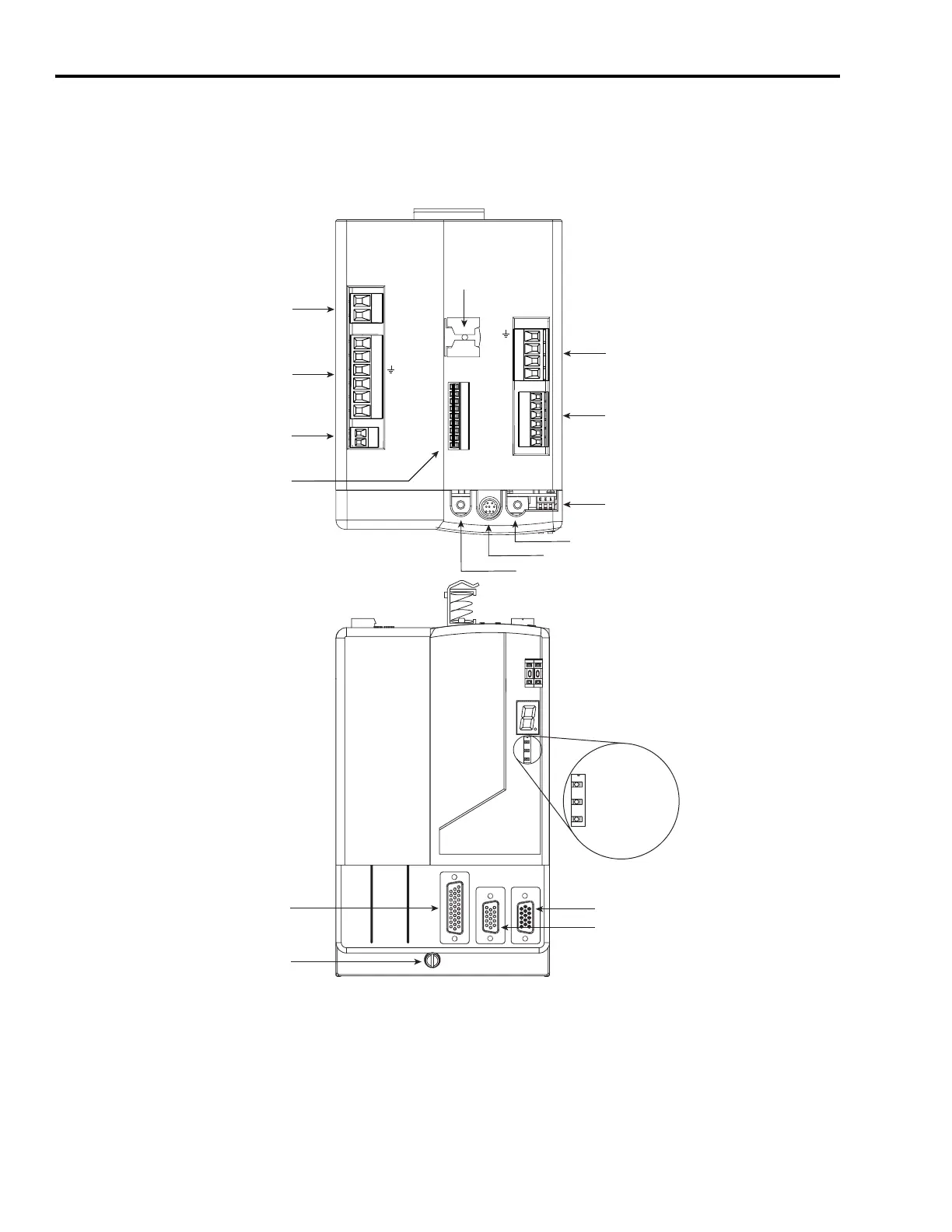
Locating IAM/AM
Connectors and Indicators
Although the physical size of the 460V modules is larger than the 230V
modules, the location of the connectors and indicators is identical.
Integrated Axis Module Connectors and Indicators
BAUD
RATE
TX
RX
DPI
DC-
DC+
L3
L2
L1
CONT EN-
CONT EN+
W
V
U
MBRK -
MBRK +
COM
PWR
DBRK -
DBRK +
CTRL 2
CTRL 1
1 2 3 4
1 2 3 4 5 6
1 2
1 2 3 4 5 6
1 2
1 2 3 4 5 6 7 8 9
Control Power
(CPD) Connector
DC Bus / AC Input Power
(IPD) Connector
Contactor Enable
(CED) Connector
Integrated Axis Module, Top View
(2094-AM05-MP5-S is shown)
Motor Power
(MP) Connector
Motor/Resistive Brake
(BC) Connector
SERCOS Baud Rate
and Optical Power Switches
SERCOS Transmit (Tx) Connector
SERCOS Receive (Rx) Connector
DPI Connector
SERCOS
Node Address Switch
Seven-segment
Fault Status LED
Drive Status LED
COMM Status LED
Bus Status LED
Auxiliary Feedback (AF) Connector
Motor Feedback (MF) Connector
I/O (IOD) Connector
Mounting Screw
Integrated Axis Module, Front View
(2094-AC05-MP5-x is shown)
Motor Cable
Shield Clamp
Safe-off
(SO) Connector
(present only on the 2094-xCxx-Mxx-S)

 Loading...


