239 Publication 2094-UM001A-EN-P — September 2006
Appendix
E
Integrating Resistive Brake Modules
with Kinetix 6000 Drives
Introduction
This appendix provides Bulletin 2090 Resistive Brake Module (RBM)
integration procedures and interconnect diagrams specific to
Kinetix 6000 multi-axis servo-drive systems. The procedure involves
setting the time delay parameter using either RSLogix 5000 or
DriveExplorer software.
Before You Begin
These procedures assume you have mounted and wired your resistive
brake module (RBM) with the Kinetix 6000 drive system. For RBM
installation instructions, refer to the Resistive Brake Module
Installation Instructions, publication 2090-IN009.
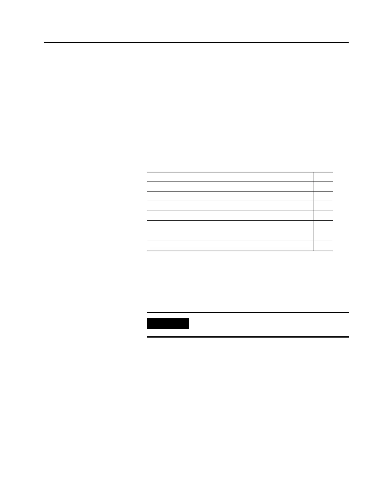
Topic Page
Introduction 239
Before You Begin 239
Understanding Safety Precautions 240
Resistive Brake Module Wiring Examples 243
The example diagram below shows Kinetix 6000 IAM, AM, and LIM (2094-ALxxS,
-BLxxS, and -XL75S) wired with the Bulletin 2090 RBM in a category 2
configuration.
244
Setting the RBM Delay Time Using DriveExplorer 252
IMPORTANT
Drive firmware v1.071 or later is required to use the RBM with
the Kinetix 6000 drives.

 Loading...


