Publication 2094-UM001A-EN-P — September 2006
Connecting the Kinetix 6000 Drive System 91
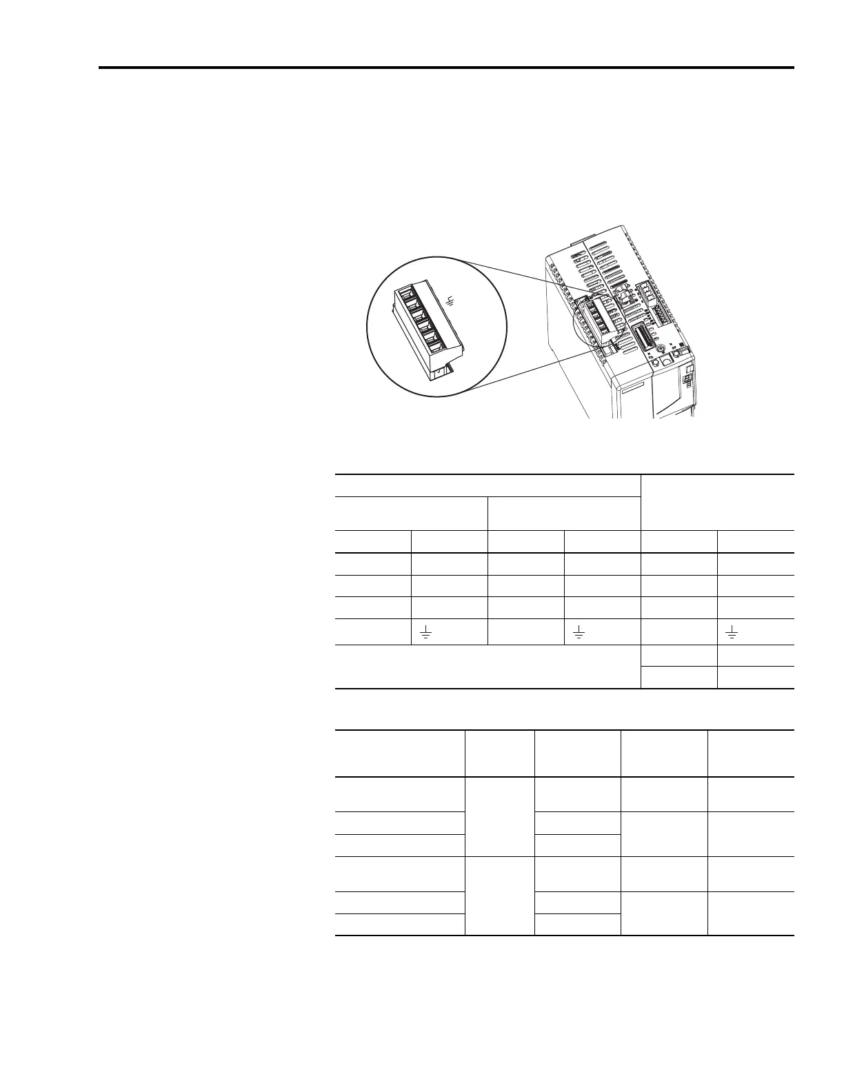
Wiring the Input Power (IPD) Connector
This example applies to an integrated axis module (IAM) or leader
IAM (dc common bus).
Integrated Axis Module (IPD connector)
Input Power (IPD) Connections
Termination Specifications
DC-
DC+
L3
L2
L1
1 2 3 4 5 6
Integrated Axis Module, Top View
(2094-BC02-M02-S is shown)
OPL Connector (LIM) or Other Three-phase Input
IPD Connector
(IAM or leader IAM)
2094-AL09
2094-BL02, -ALxxS, -BLxxS,
or -XL75S-Cx
OPL Pin Signal OPL Pin Signal IPD Pin Signal
1 L1’ 4 L1’ 6 L1
2 L2’ 3 L2’ 5 L2
3 L3’ 2 L3’ 4 L3
413
N/A
2DC+
1DC-
Integrated Axis Module
Cat. No.
Input VAC
Recommended
Wire Size
mm
2
(AWG)
Strip Length
mm (in.)
Torque Value
Nm (lb-in)
2094-AC05-Mxx-S
2094-AC09-Mxx-S
230V ac
2.5 (14) 10 (0.38)
0.5 - 0.6
(4.4 - 5.3)
2094-AC16-Mxx-S 10 (8)
16 (0.63)
2.4 - 3.0
(21.6 - 26.5)
2094-AC32-Mxx-S 25 (4)
2094-BC01-Mxx-S
2094-BC02-Mxx-S
460V ac
4.0 (12) 10 (0.38)
1.2 - 1.5
(10.6 - 13.2)
2094-BC04-Mxx-S 10 (8)
16 (0.63)
2.4 - 3.0
(21.6 - 26.5)
2094-BC07-Mxx-S 25 (4)

 Loading...


