Publication 2094-UM001A-EN-P — September 2006
Interconnect Diagrams 201
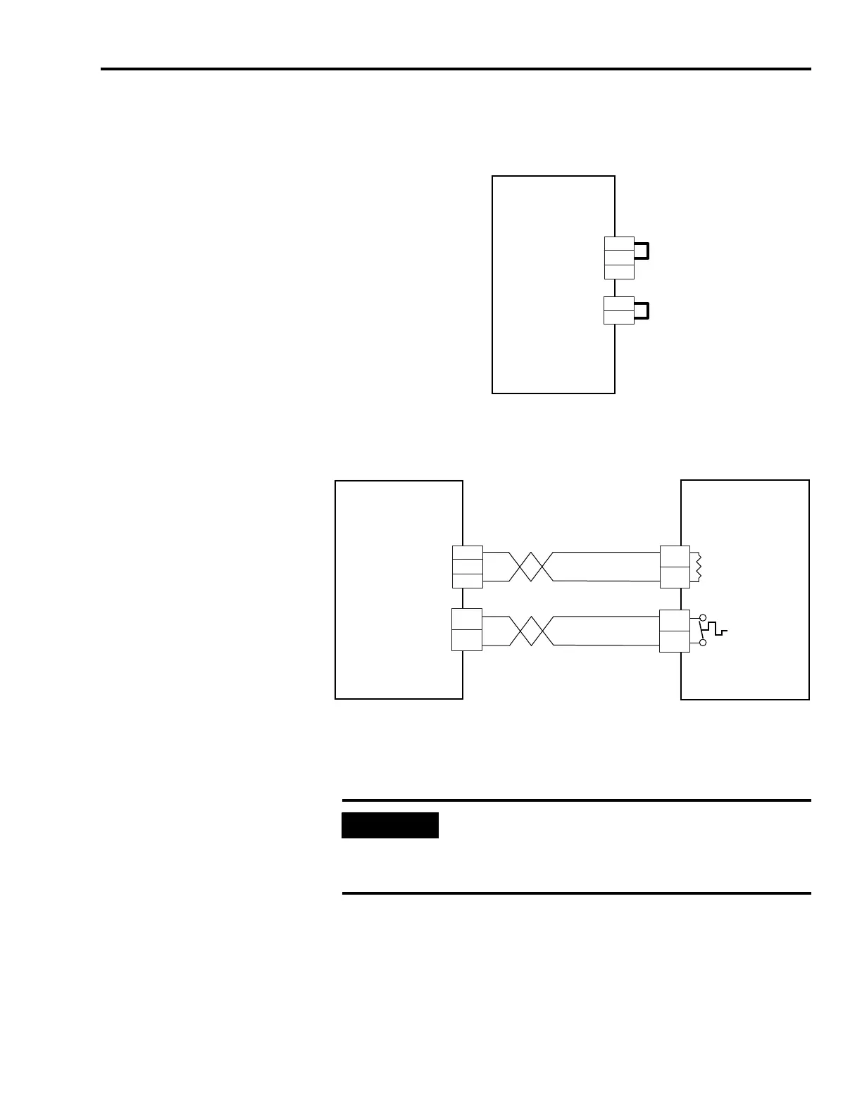
Shunt Module Wiring Examples
Shunt Module Wired for Internal Operation (default configuration)
Shunt Module Wiring Example with External Passive Shunt
Refer to External Shunt Module Specifications on page 184, for a list of
external passive shunt module catalog numbers available for the
Kinetix 6000 drives
COL
INT
DC+
TS2
TS1
2
1
3
2
1
Kinetix 6000
Shunt Module
2094-BSP2
External Shunt Resistor
(RC) Connector
External Thermal Switch
(TS) Connector
COL
INT
DC+
2
1
3
2
1
TS2
TS1
COL
DC+
Kinetix 6000
Shunt Module
2094-BSP2
External Passive
Shunt Module
External Shunt Resistor
(RC) Connector
External Thermal Switch
(TS) Connector
Resistor
Thermal
Switch
IMPORTANT
Only passive shunts with a thermal switch are wired to the TS
connector on the Kinetix 6000 shunt module. If your external
passive shunt does not have a thermal switch, leave the jumper
(default configuration) in place on the TS connector.

 Loading...


