EasyManuals Logo
Home>Rockwell Automation>Servo Drives>Allen-Bradley Kinetix 6000

Rockwell Automation Allen-Bradley Kinetix 6000 User Manual

Rockwell Automation Allen-Bradley Kinetix 6000
268 pages
To Next Page IconTo Next Page
To Previous Page IconTo Previous Page
Page #212 background imageLoading...
Page #212 background image
Publication 2094-UM001A-EN-P — September 2006
212 Interconnect Diagrams
System Block Diagrams
This section provides block diagrams of the Kinetix 6000 modules. For
block diagrams of the line interface module (LIM) and resistive brake
module (RBM), refer to Additional Resources on page 10 for the
documentation available for those products.
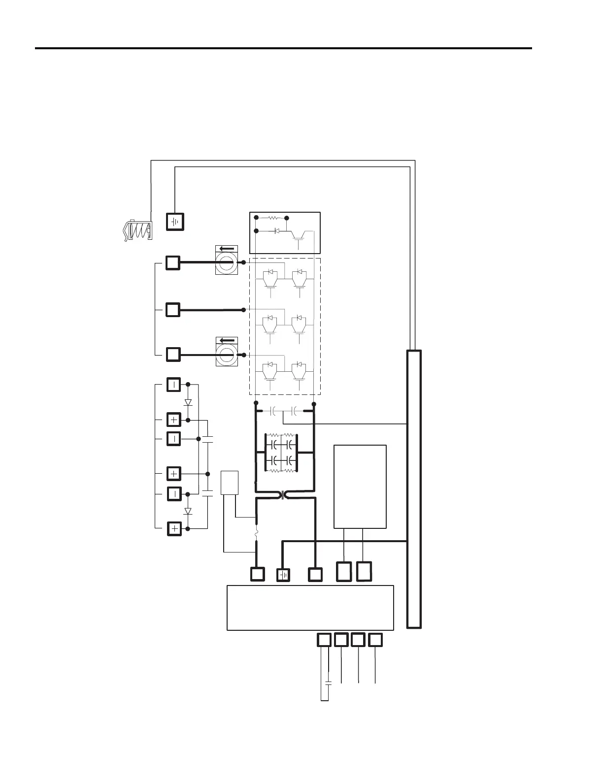
IAM/AM (inverter) Block Diagram
POWER
RAIL
DC+
DC-
WV
U
CTRL 1
CTRL 2
SYSOK
CONV_ID (5)
GSHUNT (2)
CAN (2)
DBRK
MBRK
FUSE_OK
SMPS
PWR
Three-phase Motor Output
Motor/Resistive Brake Connections
Shunt Circuit
(460V only)
Inverter Section
Motor Shield Clamp
Common Mode
Choke
(460V only)
+/-12V (Control)
+24V (Customer I/O)
+9V, +5V (Motor Feedback)
Chassis

Table of Contents

Other manuals for Rockwell Automation Allen-Bradley Kinetix 6000

Questions and Answers:

Question and Answer IconNeed help?

Do you have a question about the Rockwell Automation Allen-Bradley Kinetix 6000 and is the answer not in the manual?

Rockwell Automation Allen-Bradley Kinetix 6000 Specifications

General IconGeneral
BrandRockwell Automation
ModelAllen-Bradley Kinetix 6000
CategoryServo Drives
LanguageEnglish

Related product manuals