Publication 2094-UM001A-EN-P — September 2006
114 Connecting the Kinetix 6000 Drive System
Understanding Resistive
Brake Module Connections
Follow these guidelines when wiring your Bulletin 2090 Resistive
Brake Module (RBM).
If your application requires an RBM and you are wiring to a Kinetix
6000 IAM/AM drive, then refer to the following:
• Resistive Brake Modules on page 42.
• Resistive brake module to Kinetix 6000 drive interface cable
(catalog number 2090-XXNRB-xxFxPx).
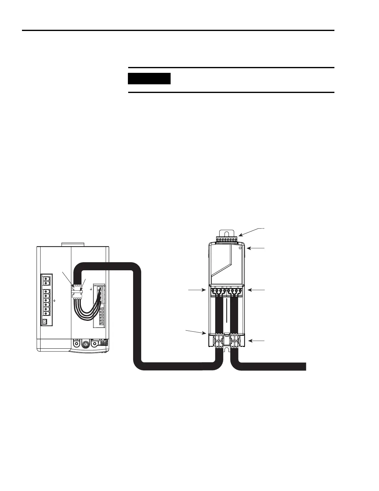
• The The example diagram below shows Kinetix 6000 IAM, AM,
and LIM (2094-ALxxS, -BLxxS, and -XL75S) wired with the Bulletin
2090 RBM in a category 2 configuration. in Appendix E.
• The installation instructions provided with your RBM, publication
2090-IN009.
Resistive Brake Module Connections
IMPORTANT
To ensure system performance, run wires and cables in the
wireways as established in Chapter 2.
BAUD
RATE
TX
RX
DPI
DC-
DC+
L3
L2
L1
CONT EN-
CONT EN+
CTRL 2
CTRL 1
W
V
U
MBRK -
MBRK +
COM
PWR
DBRK -
DBRK +
1 2 3 4
I/O
(TB3) Connections
Contactor Status LED
Motor Connection
(TB2) Connector
Drive Connection
(TB1) Connector
Motor Cable
Shield Clamps
2090-XBxx-xx
Resistive Brake Module
(front view)
2094-xCxx-Mxx IAM or
2094-xMxx AM (top view)
To Motor
Exposed Shield Braid
Under Clamp
2090-XXNRB-xxFvPx
RBM/Kinetix 6000 Interface Cable
Motor Power
Cable Clamp
(exposed shield
braid under clamp)
Tie Wrap
Bulletin 2090 Motor Power Cable

 Loading...


