Publication 2094-UM001A-EN-P — September 2006
Kinetix 6000 Connector Data 67
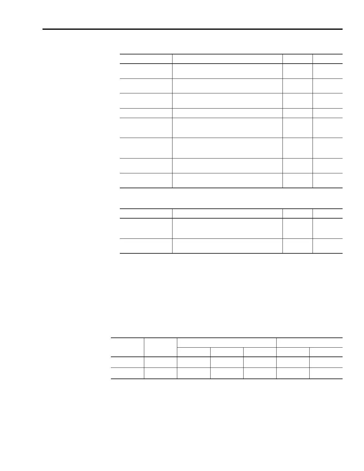
AM, BM, and IM Input Specifications for TTL Encoders
AM, BM, and IM Input Specifications for Sine/Cosine Encoders
Feedback Power Supply
The IAM and AM power circuit board generates +5V and +9V dc for
motor and auxiliary feedback power. Short circuit protection and
separate common mode filtering for each channel is included.
Motor and Auxiliary Feedback Power Specifications
Parameter Description Min Max
AM, BM, and IM
On-state input voltage
Input voltage difference between the plus (+) input and
the minus (-) input that is detected as an on-state.
+1.0V +7.0V
AM, BM, and IM
Off-state input voltage
Input voltage difference between the plus (+) input and
the minus (-) input that is detected as an off-state.
-1.0V -7.0V
Common mode
input voltage
Potential difference between any encoder signal and
logic ground.
-7.0V +12.0V
DC current draw Current draw into the + or - input. -30 mA 30 mA
AM, BM input
signal frequency
Frequency of the AM or BM signal inputs. The count
frequency is 4 times this frequency, since the circuitry
counts all four transitions.
— 5.0 MHz
IM pulse width
Pulse width of the index input signal. Since the index is
active for a percentage of a revolution, the speed will
determine the pulse width.
125 nS —
AM, BM phase error
2.5 MHz line frequency
Amount that the phase relationship between the AM
and BM inputs can deviate from the nominal 90°.
-22.5° +22.5°
AM, BM phase error
1 MHz line frequency
Amount that the phase relationship between the AM
and BM inputs can deviate from the nominal 90°.
-45° +45°
Parameter Description Min Max
Sine/cosine
input signal
frequency
Frequency of the Sine or Cosine signal inputs. — 250 kHz
Sine/cosine
input voltage
Peak-to-peak input voltages of the Sine or Cosine
inputs.
0.5V (p-p) 2.0V (p-p)
Supply Reference
Voltage Current mA
Min Nominal Max Min Max
+5V dc EPWR_5V 5.13 5.4 5.67 10
400
(1) (3)
+9V dc EPWR_9V 8.3 9.1 9.9 10
275
(2) (3)
(1)
400 mA on the 5V supply split in any manner between the channels with no load on the 5V supply.
(2)
275 mA on the 9V supply split in any manner between the channels with no load on the 9V supply.
(3)
300 mA on the 5V supply on one channel with 150 mA on the 9V supply on the second channel.

 Loading...


