Publication 2094-UM001A-EN-P — September 2006
Start 15
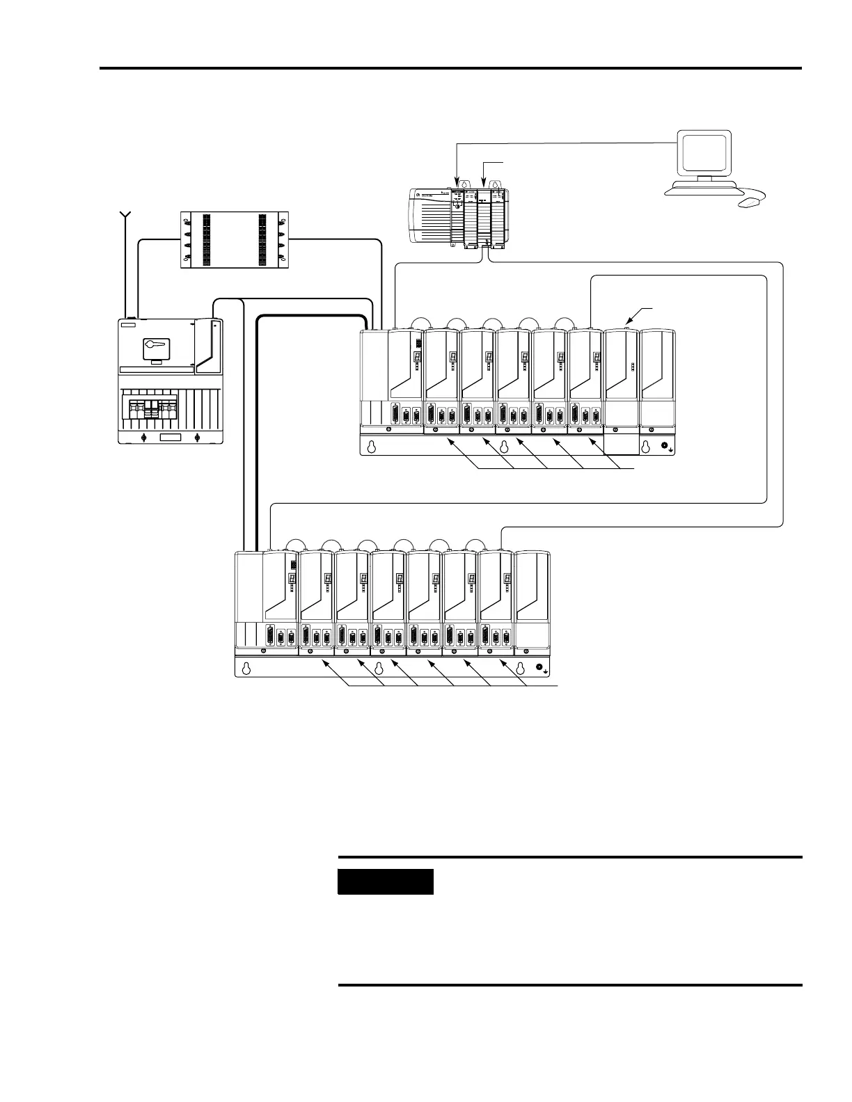
Typical DC Common Bus System Installation
In the example above, the leader IAM is connected to the follower
IAM via the dc common bus. When planning your panel layout, you
must calculate the total bus capacitance of your dc common bus
system to ensure that the leader IAM is sized sufficiently to pre-charge
the entire system.
Refer to Appendix D, beginning on page 231, for more information.
SERCOS interface
Tx (rear)
Rx (front)
OK
CP
Logix SERCOS interface Module
Logix Platform
(ControlLogix is shown)
RSLogix 5000
Software
Logix Controller Programming Network
Kinetix 6000 Multi-axis Servo Drive System
SERCOS Fiber-optic Ring
2090-SCxxx-x
Three-phase
Input Power
115/230V Control Power
Integrated
Axis Module
2094-xCxx-Mxx-S
Power Rail
(2094-PRSx is shown)
Axis Modules (5)
2094-xMxx-S
Shunt Module
(optional component)
2094-BSP2
Slot Filler Module
(required to fill any
unused slots)
2094-PRF
Integrated
Axis Module
2094-xCxx-Mxx-S
Axis Modules (5)
2094-xMxx-S
Slot Filler Module
(required to fill any
unused slots)
2094-PRF
SERCOS Fiber-optic Ring
2090-SCxxx-x
Line Interface Module
(optional component)
2094-xLxxS
AC Line Filter
2090-XXLF-xxxx
DC Common Bus
Power Rail
(2094-PRSx is shown)
Motors and other details common to both three-phase
ac and dc common bus configurations are removed.
IMPORTANT
If total bus capacitance of your system exceeds the leader IAM
pre-charge rating and input power is applied, the IAM
seven-segment LED indicator will display error code E90
(pre-charge timeout fault). To correct this condition, you must
replace the leader IAM with a larger module or decrease the
total bus capacitance by removing axis modules.

 Loading...


