Publication 2094-UM001A-EN-P — September 2006
128 Configure and Startup the Kinetix 6000 Drive System
7. Verify that the Data Rate setting matches DIP switches 2 and 3
(baud rate) as set on the IAM and AMs, or use the Auto Detect
setting.
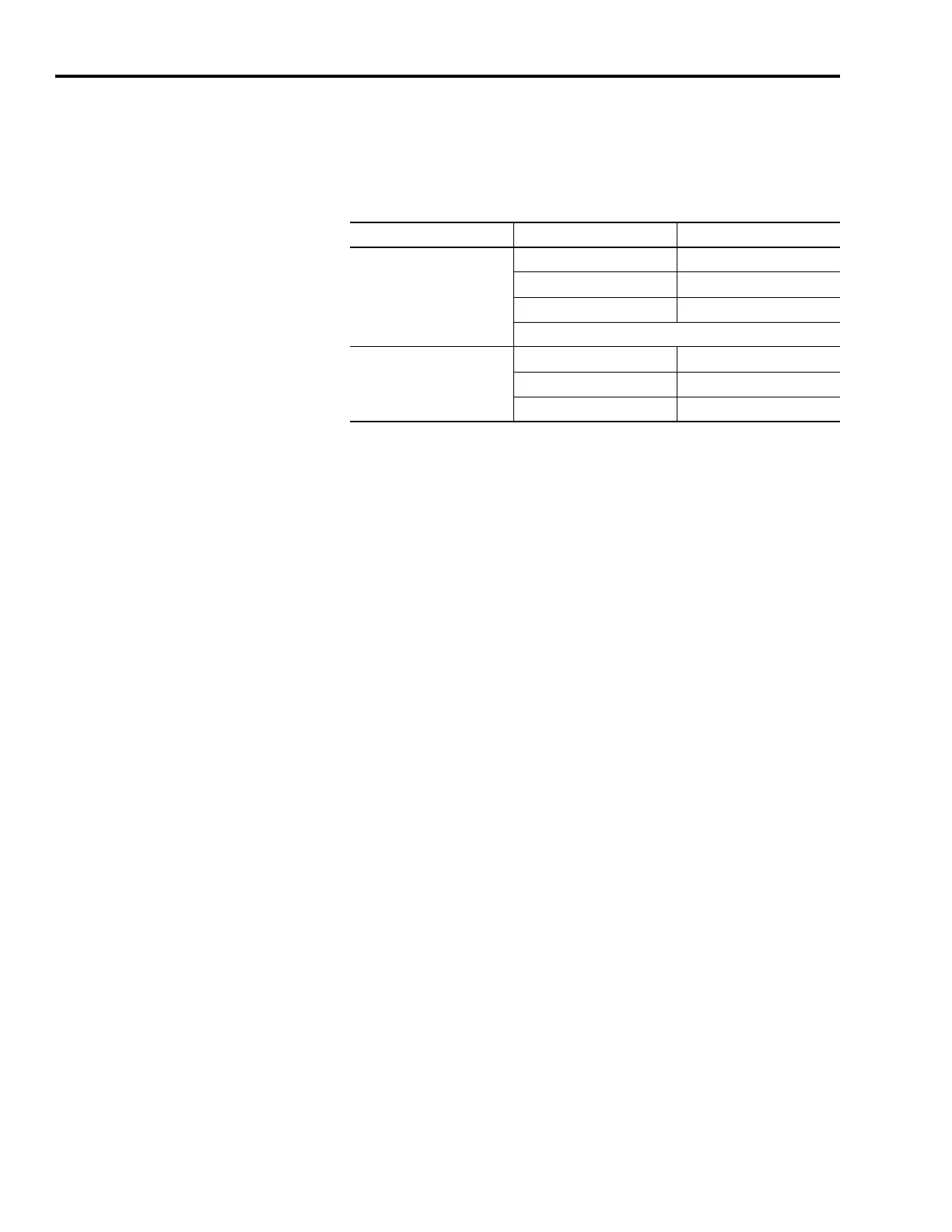
8. Set the Cycle Time according to the table below.
The number of axes/module is limited to the number of axes as
shown in Step 6.
9. Verify that the Optical Power setting (high or low) matches DIP
switch 1 as set on the IAM and AMs.
10. Set Transition to Phase.
Transition to Phase default setting is 4 (phase 4). The Transition to
Phase setting will stop the ring in the phase specified.
11. Click OK.
12. Repeat steps 1...11 for each Logix module.
Configure the Kinetix 6000 Modules
Follow these steps to configure the Kinetix 6000 modules.
1. Right-click the new Logix module you just created and select New
Module.
The Select Module dialog opens.
2. Expand the Drives category and select your 2094-xCxx-Mxx (IAM)
or 2094-xMxx (AM) as appropriate for your actual hardware
configuration.
Data Rate Number of Axes Cycle Time
4 Mbps
up to 2 0.5 ms
up to 4 1 ms
up to 8 2 ms
No support for axes 9...16
8 Mbps
up to 4 0.5 ms
up to 8 1 ms
up to 16 2 ms

 Loading...


