Publication 2094-UM001A-EN-P — September 2006
210 Interconnect Diagrams
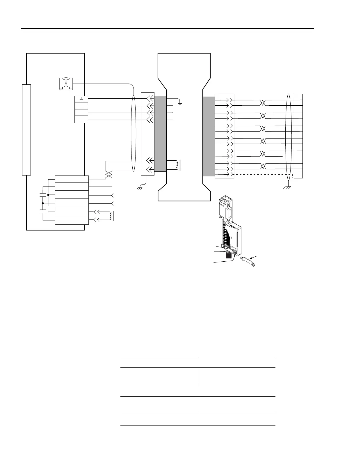
AM (230V) Wiring Example with Y-Series Motors
Controlling a Brake Example
The relay output of the Kinetix 6000 drive (MBRK± BC-5 and -6) is
suitable for directly controlling a motor brake, subject to the relay
voltage limit of 30V dc, and the relay current limit as shown in the
table below.
Brake Relay Current Limit
5
3
2
1
BR+
BR-
7
9
W
V
U
0
1
2
3
4
5
6
7
8
9
10
11
12
13
14
15
W
V
U
MBRK -
MBRK +
COM
PWR
DBRK -
DBRK +
BR+
BR-
AM+
AM-
BM+
BM-
IM+
IM-
S1
S2
GREEN
WHT/GREEN
BLACK
WHT/BLACK
RED
WHT/RED
1
2
3
4
14
6
5
10
GRAY
WHT/GRAY
12
13
8
S3
–
BROWN
WHT/BROWN
WHT/BLUE
BLUE
22
23
24
9
10
11
12
13
14
15
17
19
–
+5VDC
ECOM
DRAIN
6
5
4
3
2
1
4
3
2
1
GND
Green/Yellow
3/Black
2/Black
1/Black
Black
Black
Resistive Brake
Connections
Motor/Resistive
Brake (BC) Connector
Motor Power
(MP) Connector
Note 10
Note 15
Motor Feedback
(MF) Connector
User Supplied
24V dc (1.2A max)
Kinetix 6000
IAM (inverter) or AM
Cable Shield
Clamp
Motor
Brake
Three-phase
Motor Power
Motor
Feedback
Y-Series (230V)
Servo Motors with
Incremental Feedback
2090-XXNFY-Sxx
(flying-lead) Feedback Cable
Notes 16, 17, 18
2090-XXNPY-xxSxx
Motor Power and Brake Cable
Note 16
Motor Feedback
(MF) Connector
(IAM/AM)
Pigtail
Pigtail
Refer to low profile connector
illustration (below)
for proper grounding technique.
Low Profile Connector
(2090-K6CK-D15M shown)
Grounding Technique for
Feedback Cable Shield
Turn clamp over to hold
small cables secure.
Exposed shield and drain wire
secured under clamp.
Clamp Screws (2)
Clamp
Kinetix 6000 IAM/AM Brake Current Rating, Max
2094-AC05-Mxx, -AC09-Mxx,
2094-AMP5, -AM01, -AM02
1.0 A
2094-BC01-Mxx, -BC02-Mxx,
2094-BMP5, -BM01, -BM02
2094-AC16-Mxx, -AC32-Mxx,
2094-AM03, -AM05
1.3 A
2094-BC04-Mxx, -BC07-Mxx,
2094-BM03, -BM05
3.0 A

 Loading...


