Publication 2094-UM001A-EN-P — September 2006
Connecting the Kinetix 6000 Drive System 89
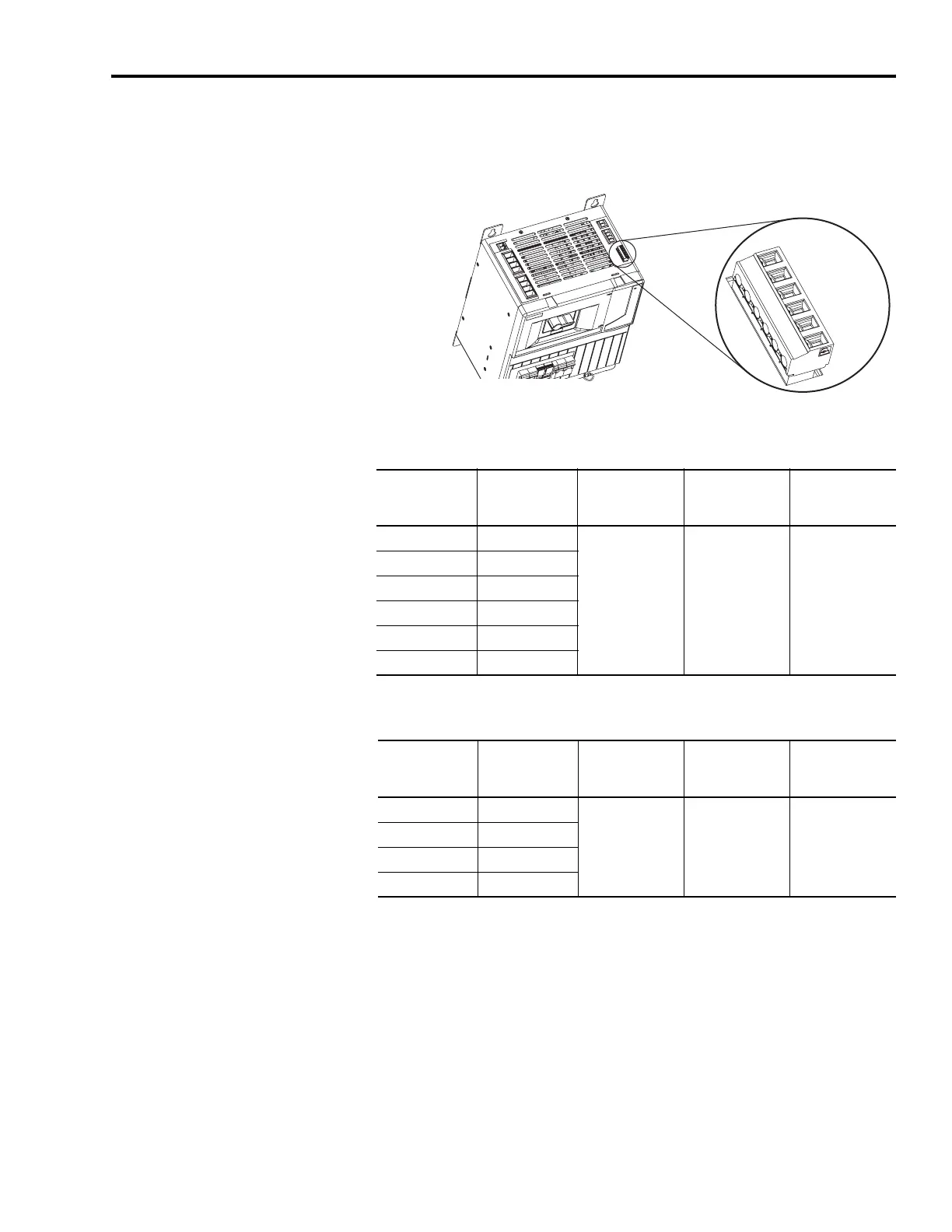
Wiring the Brake Power Output (24V dc) Connector
Line Interface Module (24V connector)
Brake Power Output (24V dc) Connector
2094-ALxxS, -BLxxS, -XL75S-Cx
Brake Power Output (24V dc) Connector
2094-AL09 and -BL02
IO_P
WR2
IO_COM2
IO_P
WR2
IO_COM2
IO_P
WR2
IO_COM2
1 2 3 4 5 6
Line Interface Module, Top View
(2094-XL75S-Cx is shown)
P1L Pin Signal
Recommended
Wire Size
mm
2
(AWG)
Strip Length
mm (in.)
Torque Value
Nm (lb-in)
1IO_PWR2
0.08-1.5
(28-16)
7.0
(0.28)
0.22-0.25 (1.9-2.2)
2IO_COM2
3IO_PWR2
4IO_COM2
5IO_PWR2
6IO_COM2
PSL Pin Signal
Recommended
Wire Size
mm
2
(AWG)
Strip Length
mm (in.)
Torque Value
Nm (lb-in)
1 MBRK PWR
2.5
(14)
10.0
(0.38)
0.5 - 0.6
(4.4 - 5.3)
2 MBRK COM
3 MBRK PWR
4 MBRK COM

 Loading...


