Publication 2094-UM001A-EN-P — September 2006
64 Kinetix 6000 Connector Data
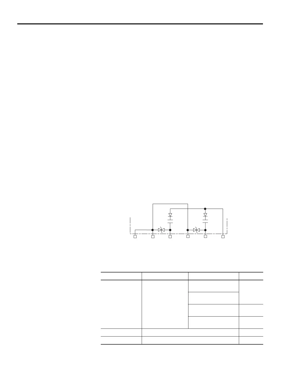
Motor/Resistive Brake Relay
Two connections are required for the (customer-supplied) motor/
resistive brake input power (BC-3 and -4) and two connections each
for the motor and resistive brake output, as shown in the figure
below. Connections are rated for +24V and current as shown in the
table below.
An active signal releases the motor brake (BC-5 and -6). The brake
signal is the same as the contactor enable signal, with the addition of
the turn-on and turn-off delays specified by the brake active delay and
brake inactive delay (configurable in RSLogix 5000 software). Refer to
Axis Module/Motor Wiring Examples beginning on page 204 and
Controlling a Brake Example on page 210 for wiring examples.
The resistive brake relay (BC-1 and -2) controls the resistive brake
module (RBM) contactor. The RBM is wired between the drive and
motor, using an internal contactor to switch the motor between the
drive and a resistive load. The RBM contact delay is the time it takes
to fully close the contactor across the motor power input lines, and
must be configured in RSLogix 5000 software. Refer to Integrating
Resistive Brake Modules with Kinetix 6000 Drives beginning on page
239 for wiring examples.
Brake Relay Circuit
(1)
Noise suppression device.
Brake Relay Output Specifications
PWR
(BC-3)
MBRK-
(BC-6)
MBRK+
(BC-5)
DBRK-
(BC-2)
DBRK+
(BC-1)
COM
(BC-4)
1
1
Kinetix 6000 IAM/AM
Parameter Description IAM/AM Max
On-state current
(1)
(1)
For motors requiring more than the maximum current specified, a relay must be added.
Current flow when the
relay is closed
2094-AC05-Mxx, -AC09-Mxx,
2094-AMP5, -AM01, -AM02
1.0 A
2094-BC01-Mxx, -BC02-Mxx,
2094-BMP5, -BM01, -BM02
2094-AC16-Mxx, -AC32-Mxx,
2094-AM03, -AM05
1.3 A
2094-BC04-Mxx, -BC07-Mxx,
2094-BM03, -BM05
3.0 A
On-state resistance Contact resistance when the relay is closed 1 Ω
Off-state voltage Voltage across the contacts when the relay is open 30V

 Loading...


