Publication 2094-UM001A-EN-P — September 2006
Connecting the Kinetix 6000 Drive System 93
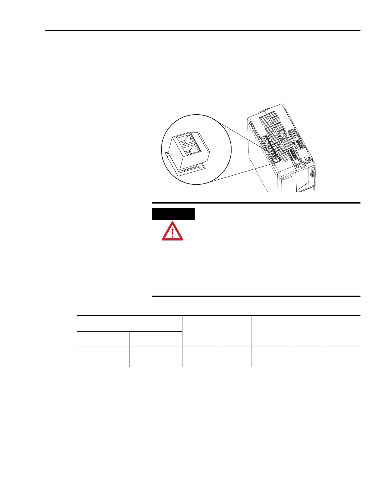
Wiring the Contactor Enable (CED) Connector
This example applies to any integrated axis module (IAM), leader
IAM, or follower IAM.
Integrated Axis Module (CPD connector)
Contactor Enable (CED) Connector
CONT EN-
CONT EN+
Integrated Axis Module, Top View
(2094-BC02-M02-S is shown)
1 2
ATTENTION
Wiring the contactor enable relay is required. To avoid personal
injury or damage to the drive, wire the contactor enable relay
into your safety control string.
Refer to Contactor Enable Relay on page 63.
In common bus configurations, the contactor enable (CED)
connections for leader and follower drives must be wired in
series to the safety control string.
For interconnect diagrams, refer to Wiring Examples beginning
on page 192.
LIM I/O (IOL) Connector or
Other Control String
CED Pin Signal
Recommended
Wire Size
mm
2
(AWG)
Strip Length
mm (in.)
Torque Value
Nm (lb-in)
2094-ALxxS, -BLxxS,
-XL75S-Cx
2094-AL09 and -BL02
IO_COM1 IO_COM 1 CONT EN-
2.5 (14)
(1)
10 (0.38)
0.5 - 0.6
(4.4 - 5.3)
COIL_E2 COIL_A2 2 CONT EN+
(1)
The actual gauge of the contactor enable wiring depends on the system configuration. Consult your machine builder, the NEC, and applicable local codes.

 Loading...


