Publication 2094-UM001A-EN-P — September 2006
Connecting the Kinetix 6000 Drive System 95
Wiring the Motor Power (MP) Connector
This example applies to axis modules (AM) and the inverter section of
integrated axis modules (IAM).
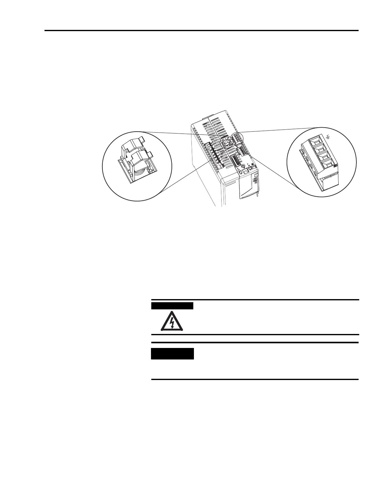
Integrated Axis Module/Axis Module (MP connector)
Cable Shield Terminations
Factory supplied motor power cables for MP-Series, TL-Series,
1326AB, F-, and Y-Series motors are shielded, and the braided cable
shield must terminate at the drive during installation. A small portion
of the cable jacket must be removed to expose the shield braid. The
exposed area must be clamped (using the clamp provided) on top of
the IAM or AM and the power wires terminated in the motor power
(MP) connector plug.
Integrated Axis Module, Top View
(2094-BC02-M02-S is shown)
W
V
U
1 2 3 4
Cable Shield Clamp
SHOCK HAZARD
To avoid hazard of electrical shock, ensure shielded power
cables are grounded at a minimum of one point for safety.
IMPORTANT
For TL- and Y-Series motors, also connect the 152 mm (6.0 in.)
termination wire to the closest earth ground.
Refer to Pigtail Terminations on page 100 for more information.

 Loading...


