ASK-T898-03-7600 Siemens Medical Systems, EM-PCS Danvers 7
7k9kXLTM.c2.CD_ROM.fm/04-99/kaupp
NOT A CONTROLLED DOCUMENT
Chapter 2: Theory of Operation
1Introduction
The SC 7000 and SC 9000XL are high-end single-board patient monitors.
The board provides the following parameters; 6 lead ECG, Respiration, two
Temperatures, SpO
2
, NBP, four IBPs, Cardiac Output, an interface
connector for an etCO
2
cartridge, and two onboard 5 watt patient isolated
ports for additional parameters. It has connectors for flat panel display,
simultaneous CRT, user interface, audio, batteries, NBP pneumatic
assembly, chart recorder, analog out, defib sync, memory card, Uarts, and
"Pick & Go" docking connector. The board contains the computer, power
supply and patient isolated front ends.
Computer Archictecture Hardware architecture of the monitors is based on a dual processor design
using two Motorola MPC860s with onboard cache. The main processor is
responsible for graphics and communications, while the second processor
is dedicated to data acquisition and algorithm processing. A DSP
subsystem preprocesses the front end data.
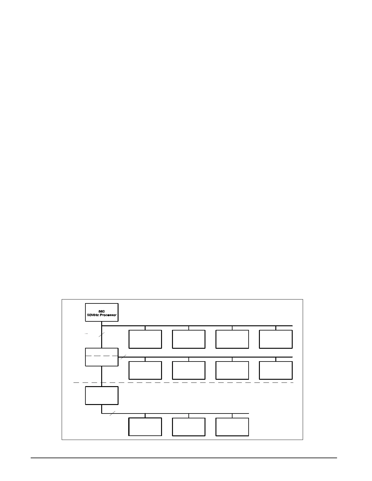
There are three major bus structures within the system; MAIN processor
bus, FRONT END bus, and REMOTE COMM bus (see Figure 2-1). The
buses operate at different speeds and efficiency. The FRONT END bus and
REMOTE COMM bus have multiple bus masters and common memory to
allow exchange between I/O devices.
The REMOTE COMM bus is special in that it may be connected and
disconnected without causing a monitor fault. This patented connect and
disconnect function of the monitor is advertised as "Pick and Go". This
allows monitors to be moved to different locations within the hospital and to
connect to multiple REMOTE COMM links without interruption of
monitoring. The traditional central station alarm function of alarming when
the patient monitor is suddenly disconnected from the network is modified
in this system by ensuring that a disconnect is intentional. A redundant
signal is used to verify a true “pick-and-go” such that a single fault does not
prevent an alarm by imitating a “pick-and-go.”
Figure 2-1SC 7000 / SC 9000XL Bus Structure
Local Memory
Memory
Expansion
Graphics I/O
860
50MHz Processor
Common Memory DSP Pod I/O
Processor Bridge
Remote Comm.
Transmitter
Remote Comm
Receiver
Common
Memory
Processor
Network
Adapter
48
Megabytes/sec
3
Megabytes/sec
16
32
32
REMOTE COMM BUS
FRONT END BUS
MAIN BUS
48 Megabytes/sec
SC 7000 /
SC 9000XL
IPS
40
40

 Loading...