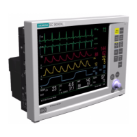
Service Manual SC 7000 and SC 9000XL Patient Monitors
34 Siemens Medical Systems, EM-PCS, Danvers ASK-T898-03-7600
NOT A CONTROLLED DOCUMENT
7k9kXLTM.c2.CD_ROM.fm/04-99/kaupp
External RAM is used for software downloader code, runtime stack,
SCC data buffers, monitor configuration data and error logs.
Monitor Connection Characteristics
The network board communicates with the attached monitor by the high
speed serial link (or by the 68302 serial channel for an SC6000 series
monitor). Because of the different characteristics of each type of link,
relays are used to select one or the other. (The default selection is the
SC6000 link.) If an SC 7000, SC 9000XL, or SC 9000 unit is detected,
the relays switch to the REMOTE COMM type link. A time filter is
applied to each signal, such that the function must be valid for a
minimum of 64 milliseconds before activating. Deactivation is
immediate.
A hardwired signal between the monitor and CPS or IDS is activated
when a cable connection is achieved. This signal is valid even if the
monitor is powered off. For an SC 7000, SC 9000XL, or SC 9000
M
onitor, a current loop is established by current flowing thru the transmit
lines, opto-isolator and receive lines. A voltage comparator activates
when the loop is sensed. The link is generated when a receive signal is
sensed by the T1 receiver.
The connection state of the monitor is defined as
• Monitor docked
• No Monitor
•Error
• Transitional
Note: If the transitional state persists for greater than one second, a
faulty docking or error condition exits
14.2EEPROMs
The CPS and IDS contain SERIAL EEPROMs which are programmed in
the factory with various configuration parameters. One contains factory-
programmed field service data and is read-only in the field. A second
EEPROM is field-programmable and contains various configuration
parameters.
14.3CPS Power Supply
The CPS power supply not only powers the network controller in the CPS
but also powers the docked patient monitor and up to two auxiliary units. It
is a line powered switching power supply capable of operating over the
range of international line voltages without having to be reconfigured.
Manual switching or fuse changing are not required.
The power supply provides a regulated +13 VDC at 7 amps to the monitor
via the docking station, and at 2.3 amps to each of 2 auxiliary docking
stations. The auxiliary docking station outputs are current limited for fault
isolation. A DC to DC converter connected to the +13 VDC output provides
a regulated +5 VDC and ±12 VDC for the network board. A fan speed
control circuit is also provided for cooling the CPS unit.
To eliminate ground potential difference resulting from the return current in
the docking station cable, the +13 VDC output has a 500 VRMS isolation
from earth ground. This isolation is maintained also in the DC to DC
converter for the +5V, ±12V outputs. An earth ground connection is made
to the monitor at the docking station for EMI suppression via the docking
station cable shield. The units connected to the auxiliary docking stations
have ground isolation in their DC to DC converters to eliminate ground
potential differences.

 Loading...


