Service Manual SC 7000 and SC 9000XL Patient Monitors
44 Siemens Medical Systems, EM-PCS, Danvers ASK-T898-03-7600
NOT A CONTROLLED DOCUMENT 7k9kXLSM.c3.CD_ROM.fm/04-99/kaupp
Caution
Be careful that the pliers or tweezers do NOT damage the tubing.
Also, do NOT put any tension on the other end of the tubing,
routed through the access hole in the back of the rear housing.
Routing of tubing inside the rear housing is critical.
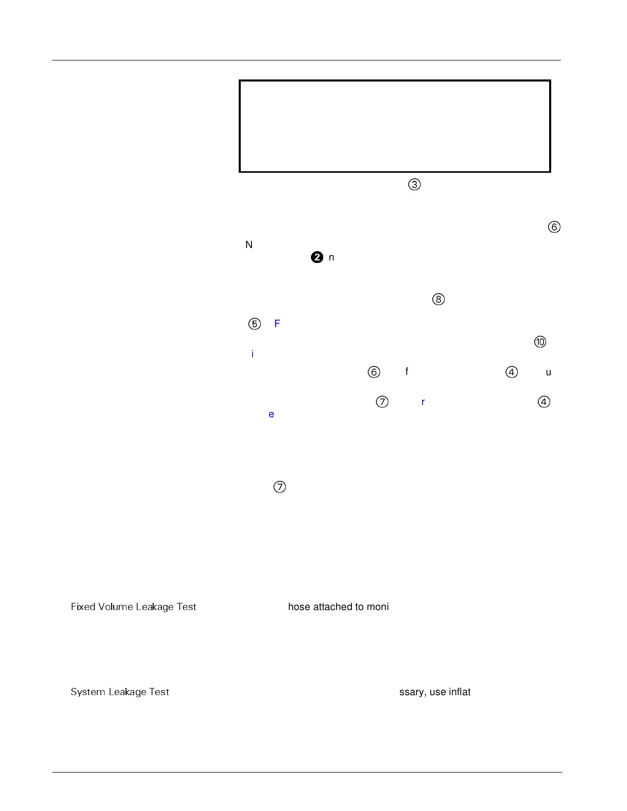
3) Carefully pull cuff connector tubing (
3
in Figure 3-4) off of cuff
connector on rear housing, observing precaution above.
4) Refer to Figure 3-1 on page 40. Using long-nosed pliers, unplug NP
subassembly cable connectors from X3 and X5 in connector cavity
6
.
Note: It may be necessary to slide ferrite filter on power cable
subassembly (
H
in Figure 3-2 on page 40) along the cable to permit
access to connectors in the connector cavity. Be sure to slide the filter
back into proper position after installing NP subassembly.
5) Note dress of cables through ferrite bead (
8
in Figure 3-4 on page 43)
on NP subassembly cables. Note also, that cable from NP coil sensor
(
5
in Figure 3-4) loops through bead twice. Remove and save bead.
6) Carefully cut ty-wrap bundling cuff connector ring filter cable (at
in
Figure 3-4) to NP subassembly cables.
7) Slide air intake filter holder
6
out of slot in retainer plate (
4
in Figure
3-4) and move cuff connector filter cable out of slot.
8) Grasp pump mounting plate (
7
in Figure 3-4) and retainer plate (
4
in
Figure 3-4), and pull NP subassembly straight out of NP compartment.
4.7.3 Installing NP Subassembly 1) Slide NP subassembly into compartment.
2) Perform steps 1 - 8 of Section 4.7.2 above in reverse order (including
re-securing of ferrite bead) to complete installation of replacement NP
subassembly. When installing new ty-wrap, be sure to secure near
plate (
7
in Figure 3-4) to keep cables in slot in plastic wall.
3) Perform an NBP characterization. Go on to section 4.7.4
4.7.4 NBP Characterization
Preparation
Set up NBP Calibration assembly (kit Art. No. 28 77 855 EE54U) as
illustated in Figure 4-1 on page 65, and assure that fixed volume and
system pneumatic leakage are within specifications.
Note: For characterization, the Siemens-recommended Pressure
Transducer Tester or manometer can be used. Accuracy of ±0.3
mmHg is required for only NBP calibration procedure.
)L[HG 9ROXPH /HDNDJH 7HVW
1) Pinch off hose attached to monitor (e.g., with a hemostat or clamp),
and using inflation bulb, increase pressure to 250 ±5 mmHg. Pinch off
hose at inflation bulb and let pressure stabilize for 1 minute.
2) Observe pressure drop for an additional 5 minutes. Drop should be <2
mmHg in 5 minutes. If not, tighten all connections and fittings, and
retest equipment for leakage. When leakage test OK, go on to step 3.
6\VWHP /HDNDJH 7HVW
3) Remove hose clamps, and if necessary, use inflation bulb to assure
that pressure on manometer is 250mmHg.
4) Again pinch off hose at inflation bulb and observe pressure drop for an
additional minute. Pressure drop should be <4mmhg. If not, service
monitor’s internal pneumatics system and retest system for leakage.
When leakage test OK, remove clamp at inflation bulb and continue.

 Loading...