Service Manual SC 7000 and SC 9000XL Patient Monitors
56 Siemens Medical Systems, EM-PCS, Danvers ASK-T898-03-7600
NOT A CONTROLLED DOCUMENT 7k9kXLSM.c3.CD_ROM.fm/04-99/kaupp
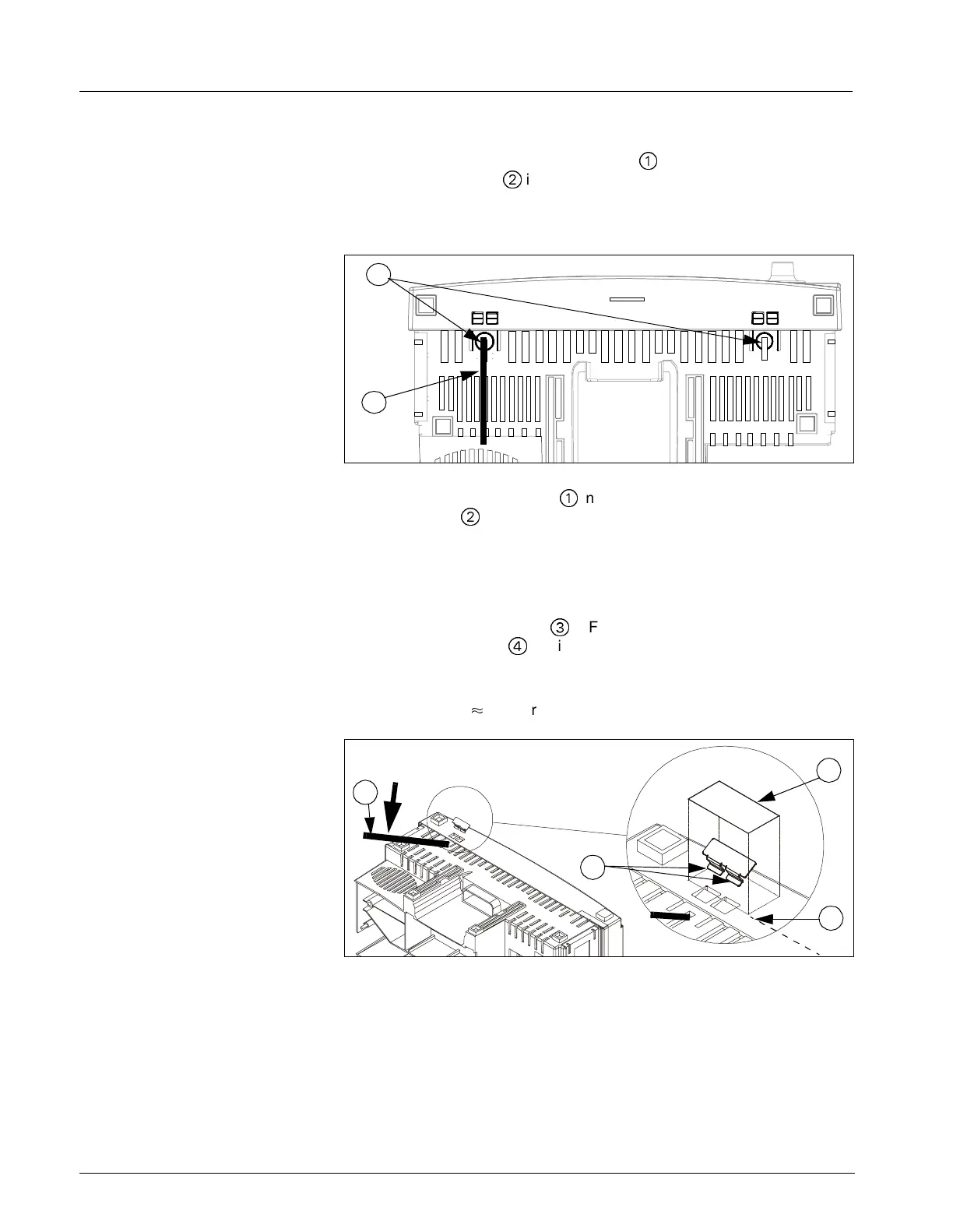
4) Turn monitor bottomside up. See Figure 3-14.
5) Insert small screwdriver or similar tool (
0
in Figure 3-14 and Figure 3-
15) into slot in tab (
@
in Figure 3-14) to use as a lever.
6) Apply slight pressure in direction illustrated by heavy arrow in Figure 3-
15 to assure tab of rear housing is securely engaged in front bezel.
Figure 3-14 SC 7000 / SC 9000XL Patient Monitor Bottom View
7) Keeping pressure on lever (
0
in Figure 3-15) , insert offset tongues of
security clip (
@
in Figure 3-15) vertically into space between bezel
and end of locking tabs in rectangular cutouts in bezel.
8) Rotate clip (hinge-like) so that offset tongues angle up under locking
tabs (to prevent tabs from being depressed) and surface of clip lies flat
on bezel.
9) Align peel-and-stick label (
3
in Figure 3-15) along edge of rectangular
tab slots (along line
4
in Figure 3-15), and press down firmly on tape
to secure clip to bezel.
Note: Do NOT attempt to depress locking tabs for at least 24 hours.
Tape requires
+
24 hours to develop full adhesive strength.
Figure 3-15Installing Security Clip and Tape
10) Remove lever, and repeat steps 3 through 7 for other set of locking
tabs on bottom of bezel.
11) Reinstall left and right side panels (see Sections 5.1.4 and 5.1.6), and
ejector shaft cover (see section Section 5.1.2).
12) Reconnect battery power and reinstall rear cover.
13) Functionally verify proper operation of the monitor before returning the
monitor to clinical service. Refer to “Chapter 4: Functional Verification
and Calibration” .
2
1
2
1
4
3

 Loading...