SC 7000 and SC 9000XL Patient Monitors Service Manual
ASK-T898-03-7600 Siemens Medical Systems, EM-PCS Danvers 79
7k9kXLSM.c5.CD_ROM.fm/04-99/kaupp
NOT A CONTROLLED DOCUMENT
3.4 ON/OFF control
problem
1) Open monitor and remove Main Processor PCB Subassembly from
rear housing to access Connector I/O PCB.
2) Check continuity of F1, F2, and F3. See Figure 5-1 on page 76.
Note: It is not necessary to remove Connector I/O PCB from rear
housing or lift one side of fuse. With power sources unplugged from
monitor and nothing plugged into X4, continuity of F1, F2, and F3 can
be checked from solder points on interior side of board.
Removing the Connector I/O PCB requires that the slide lock on the
etCO2 connector on back of the monitor be removed to release the
board. This damages the label above the connector. The damaged
label must then be removed and a replacement label (supplied with
replacement fuses) installed in its place.
3) Does F1, F2 or F3 measure as open?
Yes: Remove Connector I/O PCB, replace open fuse(s),
reassemble monitor, and perform monitor power-on check.
,I IXVHV RSHQV D VHFRQG WLP H UHSODFH IXVHV DQG 0D LQ
3URFHVVRU 3 &% 6XEDVVHPEO\
No: Inspect 44-pin connector for bent pin or misalignment. If OK,
replace Front Bezel.
4) Does replacement of Front Bezel remedy problem?
Yes: Functionally verify proper operation of monitor and return
monitor to clinical service.
No: Replace Main Processor PCB Subassembly.
3.5 Internal or external (auxiliary) battery doesn’t charge
1) When monitor connected to external power source, does battery
charger LED illuminate?
Yes: Battery possibly defective, fuse on power harness open, or
fuse on connector I/O board open. Continue to step 2.
No: Replace battery. If problem persists, replace Main
Processor PCB Subassembly. If still no charge indication,
replace Front Panel Subassembly.
2) Remove battery/NBP compartment access door and unplug battery
power cable connector from X1. See Figure 5-1 on page 76.
3) Connect external power source to monitor.
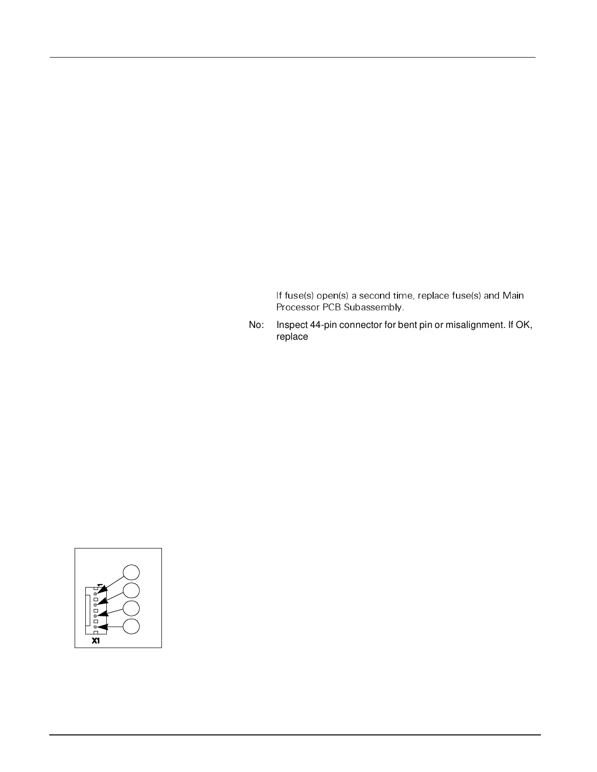
4) Refer to illustration at left.
• Measure voltage between pins 3 and 4 of X1 on Connector I/O board
to check charging voltage for main battery.
• Measure voltage between pins 1 and 2 of X1 on Connector I/O board
to check charging voltage for external battery.
5) Is voltage = 13.6 to 13.9 VDC?
Yes: For main battery, go on to step 6. For external battery, go on
to step 8.
No: Go to step 8.
6) Check continuity of in-line fuse in power cable harness.
3
4
1
2

 Loading...