Service Manual SC 7000 and SC 9000XL Patient Monitors
54 Siemens Medical Systems, EM-PCS, Danvers ASK-T898-03-7600
NOT A CONTROLLED DOCUMENT 7k9kXLSM.c3.CD_ROM.fm/04-99/kaupp
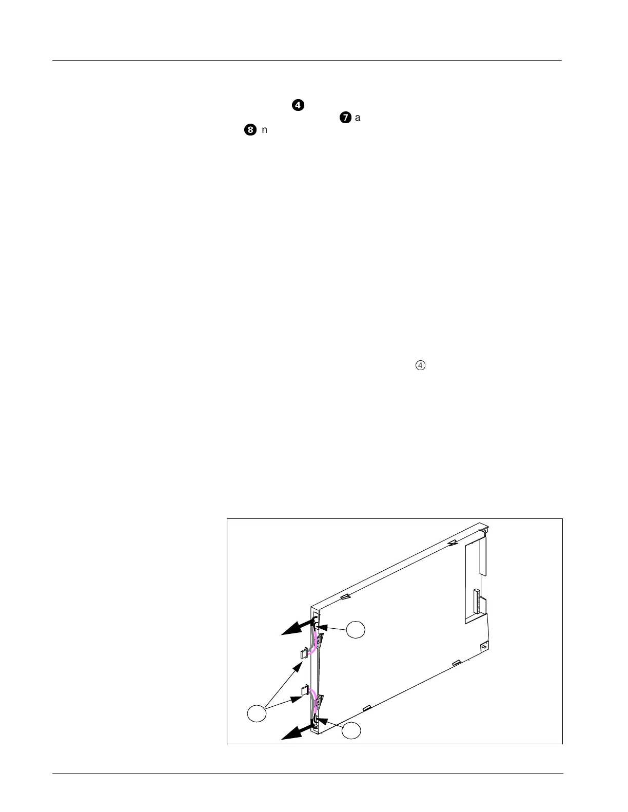
6) Refer to Figure 3-10 on page 51. Plug display screen flex cable
connector
;
into display screen subassembly PC board, and display
backlight connectors
?
and membrane switch ribbon cable connector
@
into Front Bezel PC Board.
7) Dress display backlight cables into space between display
subassembly and front bezel PC board.
8) Slide optical encoder subassembly shaft through hole in front bezel,
positioned such that keyway on shaft is toward top of panel.
9) Slide positioning washer removed in step 7 of Section 7.1.1 above
onto subassembly shaft so tab on hole in washer slides into keyway on
subassembly shaft and locking tab on washer is into hole in front bezel
above shaft.
Note: This assures that optical encoder subassembly is positioned so
that its ribbon cable connector plugs properly into the front bezel PC
board and the subassembly doesn’t rotate in subsequent use.
Note: Slide lockwasher and nut removed in step 7 of Section 7.1.1
above onto subassembly shaft, and tighten to secure subassembly in
front bezel.
10) Plug optical encoder ribbon cable connector into Front Bezel PC Board.
11) Slide retainer plate tabs into tab slots (
4
in Figure 3-11 on page 51) in
top of front bezel frame.
12) Press down on plate and slide plate right to insert tabs on right hand
side of plate into tab slots on side of front bezel frame.
13) Secure to frame using screws removed in step 1 of Section 7.1.1.
14) Reassemble monitor. Refer to Section Section 8.
7.2 Optical Encoder
Subassembly
Refer to steps step 1 through step 7 of Section 7.1.1 to remove Optical
Encoder Subassembly, and to steps step 8 through step 14 of Section 7.1.2
to install Optical Encoder Subassembly. Install new rotary knob. See
Section 4.1.
Figure 3-13 Display Screen Subassembly
1
2
2

 Loading...