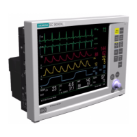
Service Manual SC 7000 and SC 9000XL Patient Monitors
78 Siemens Medical Systems, EM-PCS, Danvers ASK-T898-03-7600
NOT A CONTROLLED DOCUMENT
7k9kXLSM.c5.CD_ROM.fm/04-99/kaupp
Removing the Connector I/O PCB requires that the slide lock on the
etCO
2
connector on back of the monitor be removed to release the
board. This damages the label above the connector. The damaged
label must then be removed and a replacement label (supplied with
replacement fuses) installed in its place. It is necessary to remove a
Connector I/O PCB only if a fuse needs to be replaced.
7) Is F3 open? (>5Ω)
Yes: Replace fuse, reassemble monitor, and continue to step 8.
No: Replace Main Processor PCB Subassembly.
8) Does monitor power ON using only main battery as power source?
Yes: Return monitor to service after checkout.
No: Replace fuse and Main Processor PCB Subassembly.
3.3 With external battery
installed, monitor fails
to function on battery
power for prescribed
time.
1) Remove external battery and measure battery terminal voltage.
2) Is voltage = 11.6 to 13.8 VDC?
Yes: Continue to step 5.
No: Battery is not charged to 12VDC. Reinsert external battery
into monitor, and go to Section 3.5.
3) Remove back cover, and with external power plugged into monitor
check voltage between pins 1 and 2 of X1. See Figure 5-1 on page 76
4) Is voltage = 13.6 to 13.9 VDC?
Yes: Go to Section 3.2.
No: Continue to step 5.
5) Check continuity of F2. See Figure 5-1 on page 76.
Note: It is not necessary to remove Connector I/O PCB from rear
housing or lift one side of fuse. With power sources unplugged from
monitor and nothing plugged into X1, continuity of F2 can be checked
from solder points on interior side of board.
Removing the Connector I/O PCB requires that the slide lock on the
etCO2 connector on back of the monitor be removed to release the
board. This damages the label above the connector. The damaged
label must then be removed and a replacement label (supplied with
replacement fuses) installed in its place. It is necessary to remove a
Connector I/O PCB only if a fuse needs to be replaced.
6) Is F2 open? (>5Ω)
Yes: Replace fuse, reassemble monitor, and continue to step 8.
No: Replace Main Processor PCB Subassembly.
7) Install charged external battery and unplug power harness from either
terminal of main battery.
8) Does monitor power ON using only external battery as power source?
Yes: Reconnect power harness cable to main battery, and return
monitor to service after checkout.
No: Replace fuse and Main Processor PCB Subassembly.

 Loading...


