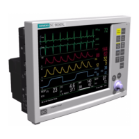
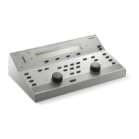
Service Manual SC 7000 and SC 9000XL Patient Monitors
12 Siemens Medical Systems, EM-PCS, Danvers ASK-T898-03-7600
NOT A CONTROLLED DOCUMENT
7k9kXLTM.c2.CD_ROM.fm/04-99/kaupp
2.10.3 SC 9015 Interface The SC 9015 Interface is implemented in the main processor
communication channels. SCC2 has been dedicated as the channel
between the remote monitor and the base unit, and provides a full duplex
transmit/receive channel from/to the remote monitor. This interface enables
the fixed keys and rotary knob on the remote display to control the main
unit, in parallel with controls on the main unit.
2.10.4 Fast Analog Output The ANALOG OUT interface consists of two identical channels. Each
ANALOG OUT channel provides a 12 bit D/A function. The design uses a
dual DAC to produce the D/A conversion. The sampled analog data is then
passed through a 2 pole low pass filter. The analog output has a maximum
delay of 20ms, and can be used for a defibrillator or balloon pump.
Separate Pacer Spike generation circuits for analog outputs 1 and 2 are
provided.
2.10.5 HiFi Audible Alarm Interface The Audible alarm interface consists of an FM synthesis and Audio DAC
chip set. There is also power amplifier drive circuitry for the two speaker
interfaces: the internal speaker located in the base unit and the speaker
located in the remote CRT. Circuitry has been included to provide a
mechanism for automatically generating an error tone when a watchdog
failure occurs via the piezo alarm (see Section 6.1.8)).
The chip is loaded with tone frequency, pitch, harmonics, and volume
information by the host processor, which controls the duration of the tone.
The audio DAC converts the received sampled tone data and produces a
sampled analog representation of the tone data.
The local speaker interface (also designated as main speaker interface) is
designed for an 8 ohm speaker load. This local speaker interface produces
1 watt of power into an 8 ohm load, and has thermal shutdown capability.
The remote speaker interface is designed to produce a 1Vrms maximum
signal into a 1 kohm load, and provides an ac coupled output.
2.10.6 LED/Status Interface Five LEDs provide information in the present SC 7000 and SC 9000XL
configurations. Two are dedicated to the front end processor, to the DSP,
and two to the main processor.
2.10.7 QRS Sync Out Interface A QRS sync output is provided. The QRS SYNC OUTPUT is an open
collector type output driver that is pulled up to +12 volts (active HIGH). The
output is initialized to Gnd on reset or power on.
This QRS signal is available via an external connector mounted on the main
PC board. High level = +6V min (10KΩ load), +12.6V (no load); Low level
(no QRS) = 1V @ 5ma.
2.10.8 Local Alarm Out Interface A Local Alarm output is provided. This Local Alarm Output is an open
collector type output driver that is pulled up to +12 volts. The output is
initialized to ground (0 volts) on reset or power on (active HIGH).
Loopback status is available via a status read command.
The Local Alarm Out signal is available via an external connector mounted
on the main PC board.
2.10.9 Remote Alarm Out Interface
for Nurse Call
The Remote Alarm Output Interface is located in the CPS/IDS subsystem.
This output is an open collector output with a +12V pullup resistor, fed from
the monitor. The Remote Alarm Output is silenced when a monitor is
undocked.

 Loading...


