SC 7000 and SC 9000XL Patient Monitors Service Manual
ASK-T898-03-7600 Siemens Medical Systems, EM-PCS Danvers 15
7k9kXLTM.c2.CD_ROM.fm/04-99/kaupp
NOT A CONTROLLED DOCUMENT
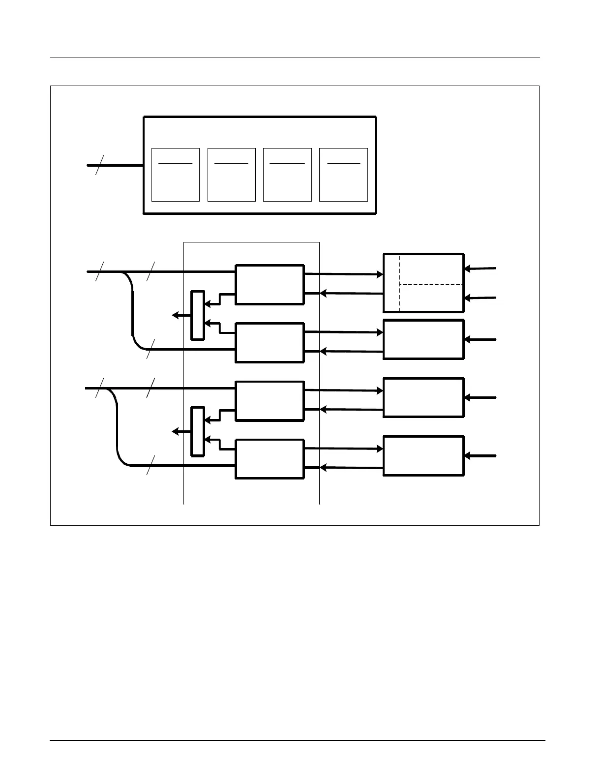
Figure 2-6 POD Communications
5 POD COM
Subsystem
A pod is a front end device that acquires data for a particular set of
parameters. A pod may contain a processor and return preprocessed data
or it may provide raw A/D samples.
Refer to Figure 2-6.
5.1 Overview
Data acquisition of the monitor is controlled by several DMA controllers that
operate on circular buffers residing in common memory on the FRONT
END bus. There are four channels, each allocated a 16 bit transmit buffer
and a 16 bit receive buffer. It takes four 32 bit transfers to update one
location in every buffer, since each access consists of high and low data
from different channels. The transmit buffer tells the pod either what sample
to take or to change a control setting. The receive buffer contains a/d
samples and status information from the pod. A control register in the FPGA
sets a mux to the DSP’s communication port and connects the selected pod
com channel.
Front
End
Bus
Channel A
Data In
Data Out
Channel D
Data In
Data Out
Channel C
Data In
Data Out
Channel B
Data In
Data Out
Memory Buffers
Common RAM
32
DMA
Channel A
Pod
Com
DMA
Channel B
Pod
Com
DMA
Channel C
Pod
Com
DMA
Channel D
Pod
Com
M
U
X
M
U
X
32
32
16
1616
16
16
DSP
Serial
CH A & B
DSP
Serial
CH C & D
M
U
X
64K Samples/sec
64K Samples/sec
64K Samples/sec
64K Samples/sec
64K Samples/sec
64K Samples/sec
64K Samples/sec
64K Samples/sec
Pod Com
Isolation
Pod Com
Isolation
Pod Com
Isolation
Pod Com
Isolation
Cartridge
Interface
MultiMe
Front En
HemoMe
Front En
etCO
2
Cartridge
Pod 1
Pod 2
(16 bit Samples)
Main FPGA

 Loading...