SC 7000 and SC 9000XL Patient Monitors Service Manual
ASK-T898-03-7600 Siemens Medical Systems, EM-PCS Danvers 43
7k9kXLSM.c3.CD_ROM.fm/04-99/kaupp NOT A CONTROLLED DOCUMENT
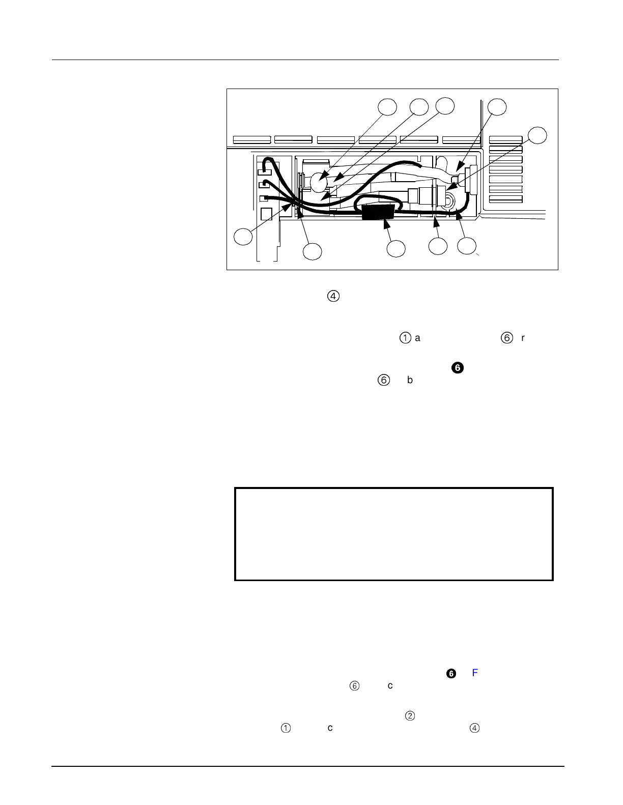
Figure 3-4 NP Subassembly in Rear Housing
4.7 NP Filters and Pump
Subassembly
The NP subassembly,
4
in Figures 3-1 and 3-2, is housed in a
compartment above the external battery on the back of the monitor. Use the
following procedure to replace filters and/or the NP subassembly.
4.7.1 Replacing Manifold and Air
Intake Filters
Refer to Figure 3-4. The manifold filter
0
and air intake filter
6
are
mounted directly on the NP pump subassembly.
1) Remove and save three Phillips-head screws,
=
in Figure 3-2 on
page 40, securing back cover
6
on back of monitor, and remove
cover.
2) Remove cap from holder of filter to be replaced.
Note: If replacing air intake filter, slide holder out of retainer plate
before removing cap.
3) Using long-nosed pliers or tweezers, remove and discard filter,
4) Insert replacement filter into holder. Observe following precaution.
Caution
The filter has a hole in one end. Insert the filter hole-end first, so
that the hole is at the internal end of the holder and the end
without the hole is at the cap end of the holder. This provides for
proper filtering with minimal restriction of air flow.
5) Reinstall cap on filter holder.
Note: If replacing air intake filter, slide holder back into slot in retainer
plate ➅ after reinstalling cap.
6) Reposition back cover on monitor, and reinstall three securing screws
removed in step 1.
4.7.2 Removing NP Subassembly 1) Remove and save three Phillips-head screws,
=
in Figure 3-2 on page
40, securing back cover
6
on back of monitor, and remove cover.
2) Refer to Figure 3-4, and using long-nosed pliers, tweezers, or similar
tool, carefully pull transducer tubing
@
off of mounting port on filter
housing
0
, and back through slot in retainer plate
4
. Observe the
following precaution.
6
4
7
1 2 3
5
8
9
10

 Loading...