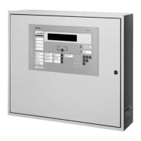
SC 7000 and SC 9000XL Patient Monitors Service Manual
ASK-T898-03-7600 Siemens Medical Systems, EM-PCS Danvers 49
7k9kXLSM.c3.CD_ROM.fm/04-99/kaupp NOT A CONTROLLED DOCUMENT
Caution
The funnel must be removed before attempting to remove the
Main Processor PCB Subassembly.
• The Front Bezel Subassembly, when installed, further locks the Main
Processor PCB Subassembly in place and completes mechanical
integration of the monitor’s several internal subassemblies.
6.2.1 Removing Main Processor
PCB Subassembly
1) After opening monitor, see Section 5, set rear housing subassembly
bottomside down on a clean flat surface.
2) Using long nose pliers, carefully pull NBP tubing off of transducer port
(
0
in Figure 3-9 on page 50) and out of its routing channel. Note
routing of NBP tubing. Use exactly same routing when
reassembling monitor. Save grommet for use in reassembly. Tuck
tubing temporarily under monitor handle on top of housing (to keep it
out of the way).
3) Using small common-blade screwdriver, depress locking tabs near left
and right sides of funnel through slots on top edge of rear housing (
H
in Figure 3-9) to release funnel, and slide funnel out of rear housing.
4) Reaching through rectangular slot on right hand side of rear housing,
apply pressure behind the 14-pin mini-champ connector housings on
main PCB to unplug Main Processor PCB Subassembly from X4 on
the Connector I/O PC Board.
5) Grasp handle on Main Processor PCB support (
3
in Figure 3-9), and
pull sub-assembly straight out from rear housing to slide connectors
on left side of main PCB out of channels in rear housing and remove
subassembly.
6) Place Main Processor PCB Subassembly in static-protected
environment.
6.2.2 Installing Main Processor
PCB Subassembly
Reverse procedure of Section 6.2.1 to install Main Processor PCB
Subassembly.
Note: Mating Main Processor PCB Subassembly into Rear Housing
Subassembly requires that Pod Com connectors (
5
in Figure 3-9)
align properly in channels (
<
in Figure 3-9) in left side of rear housing.
$OVR EH YHU\ FDUHI XO WR OLPLW DQ\ H[FHVV SQHXPDWLF WXELQJ LQ WKH DUHD
EHWZHHQ WKH JURPPHW DQG WKH 1%3 SUHVV XUH WUDQVGXFHU WR PLQLPL]H
WKH SRVVLELOLW\ WKDW WKH WXELQJ FDQ EHFRPH SLQFKHG EHWZHHQ WKH KHDW
VLQN DQG IURQW SDQHO V XEDVV HPEO\ LQ WKH UHDV VHPEO\ SURFHVV
6.3 Replacing Rear
Housing
Replacing the rear housing is a matter of removing subassemblies and
components (except the Connector I/O PCB) from the old rear housing, and
installing them in the new Rear Housing Subassembly in accordance with
procedures given in appropriate sections above. Perform the procedures in
the order given in the following steps:
N. B. The monitor’s serial number is electronically embedded in a chip
on the Connector I/O PCB and also printed on a label on back of the
rear housing. The replacement Rear Housing Subassembly must be
specially prepared at the factory, with an identical serial number,

 Loading...