Service Manual SC 7000 and SC 9000XL Patient Monitors
8 Siemens Medical Systems, EM-PCS, Danvers ASK-T898-03-7600
NOT A CONTROLLED DOCUMENT
7k9kXLTM.c2.CD_ROM.fm/04-99/kaupp
1.1 Main Processor Bus
The Main processor bus is a 32 bit data bus connecting the MPC860 to its
main bank of 16 meg DRAM memory. The Program for the monitor is stored
in 8 meg Flash memory and uploaded to DRAM during initialization. The
DRAM is optimized for multiple word transfers allowing efficient cache fills.
This bus has an optional daughter card connector allowing expansion of the
main memory space. The graphics controller is connected to this bus to
allow high bandwidth access to video memory. The bus has a max
bandwidth of 40 megbytes/sec.
This bus also has an I/O space implemented in an FPGA. These functions
include audio, chart recorder interface, keypad and rotary knob interface,
and EEPROM. The EEPROM contains serial #’s, calibration constants and
configurations. The I/O space also includes the Bridge to the FRONT END
bus and a port to the REMOTE COMM bus. The Bridge to the FRONT END
bus is unidirectional. This means that the Main processor may read and
write to the FRONT END bus, but the Front end processor can not access
the MAIN bus.
1.2 Front End Bus
The Front End bus is a 32 bit data bus connecting the second MPC860 to
its main bank of 4 meg DRAM memory. The program for this processor is
downloaded from the main processor during initialization. The DRAM is
optimized for multiple word transfers allowing efficient cache fills. Both
processors contain 512K of battery-backed SRAM for trend and other
patient data storage. Data is exchanged through the common memory.
This bus has multiple bus masters that include the following:
• Front End 860
• Main 860
• DSP DMA
• POD Comm DMA (a POD is a configured front end)
• DRAM Refresh
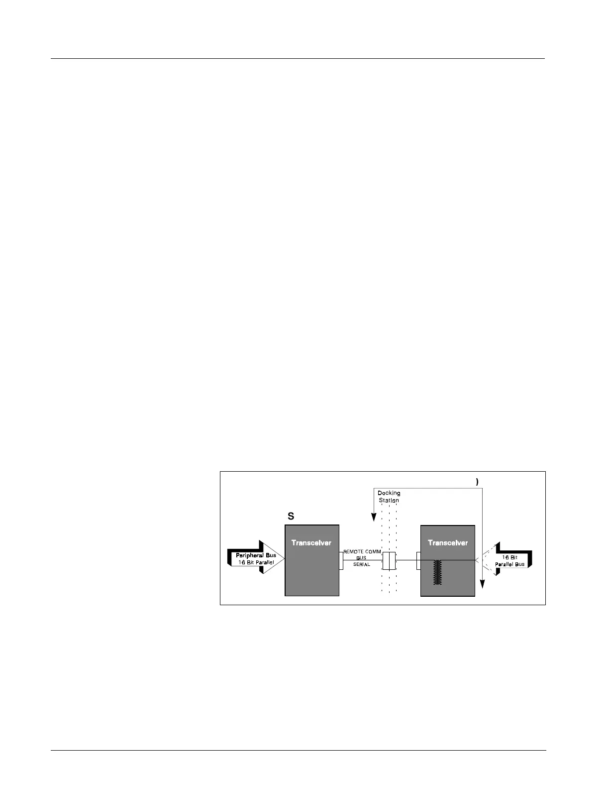
Figure 2-2 REMOTE COMM Bus
1.3 REMOTE COMM Bus
The REMOTE COMM bus (Figure 2-2) is a bus extender used to extend the
main bus to a second chassis. The parallel address bus and data bus are
serialized using high speed FDDI transceivers, allowing virtual parallel
access to a remote parallel bus. The parallel bus is located in the CPS
communication power supply module or in the Iinfinity Docking Station
(IDS). This bus interfaces to a network controller and other local serial
buses including MIB, lGraphics, Gas Monitoring, and other peripherals. The
host is stalled until completion of all read operations, but is released after a
write is latched to be serialized.
CPS
IDS (= Dk. Sta. + XCVR
SC 9000X
SC 7000/

 Loading...