Service Manual SC 7000 and SC 9000XL Patient Monitors
26 Siemens Medical Systems, EM-PCS, Danvers ASK-T898-03-7600
NOT A CONTROLLED DOCUMENT
7k9kXLTM.c2.CD_ROM.fm/04-99/kaupp
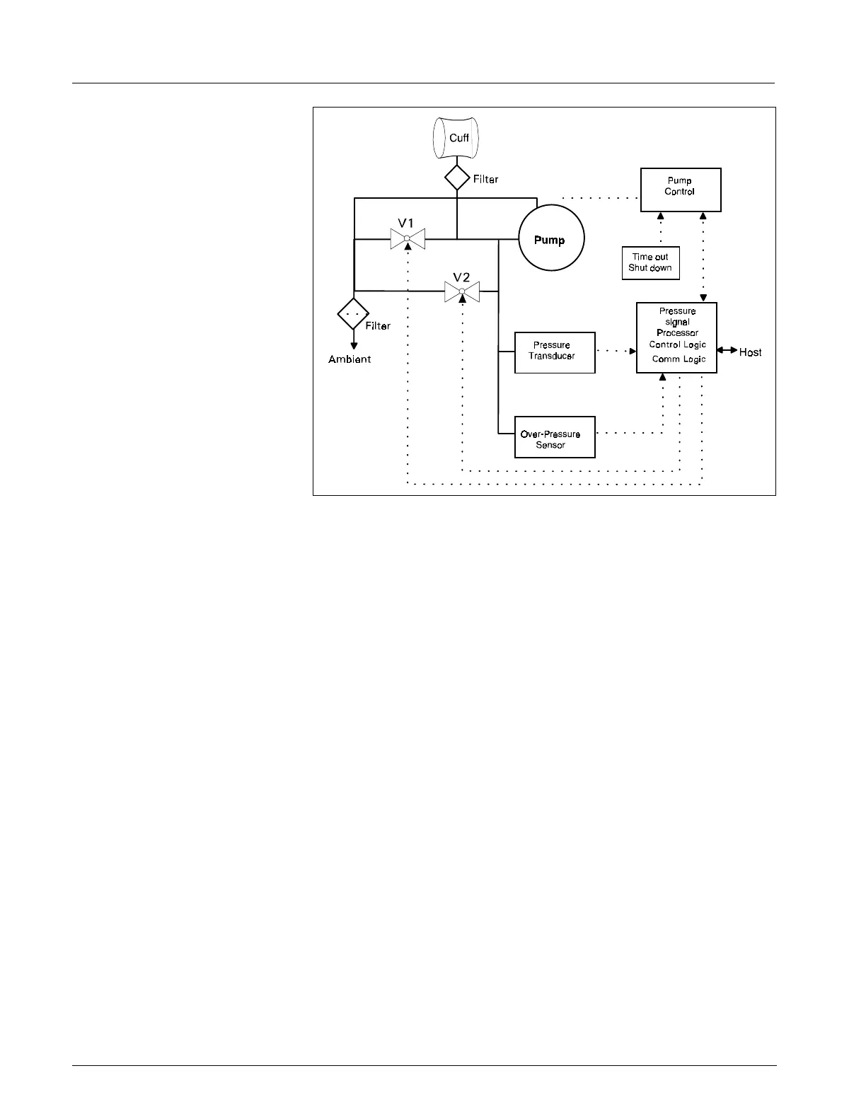
Figure 2-13 NBP Functional Block Diagram
9 NBP
Refer to Figure 2-13.
9.1 Introduction
The NBP design measures blood pressure non-invasively using an
inflatable cuff and the oscillometric method. The NBP algorithms are
performed in the front end processor. The NBP circuit contains two
pressure transducers which measure the hose pressure. The second
redundant pressure sensor is used to measure overpressure for safety.
This pressure transducer is mounted in the power section while the other
pressure transducer is mounted in the MultiMed front end. A plastic
manifold connects the two transducers together and to the pneumatic
assembly in the rear case. The MultiMed front end A/D samples the
pressure transducer.
9.2 Pneumatic
Subassembly
The pneumatic subassembly consists of two modulating solenoid valves
(V1, V2), a pump (P1), a filter, and a manifold. The manifold provides the
interconnection of the air passages between the individual components and
provides for their mechanical mounting. It also provides an acoustic
attenuation of the valve and pump noise. The filters prevent contamination
from entering the pneumatic system from the cuff hose or ambient air.
P1 provides the pressurized air to inflate the blood pressure cuff. V1 and
V2 are used to control the air flow during the de-flation phase of a blood
pressure measurement. V1 is a normally closed exhaust valve with a
relatively small orifice. V2 is a normally open exhaust valve with a
comparatively large orifice.
When a blood pressure measurement is initiated V2 is closed, P1 is turned
on and the rising cuff pressure is monitored via pressure transducers.
When the pressure has reached the target inflation pressure, P1 is turned
off. Neonate inflation cycles are identical except that a speed control circuit
is used to reduce the pump output to approximately 15% of the adult mode.
After the inflation, there is a short delay after the pump stops to allow

 Loading...