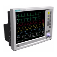
SC 7000 and SC 9000XL Patient Monitors Service Manual
ASK-T898-03-7600 Siemens Medical Systems, EM-PCS Danvers 55
7k9kXLSM.c3.CD_ROM.fm/04-99/kaupp NOT A CONTROLLED DOCUMENT
7.3 Backlight Lamps
The backlight fluorescent lamps are located inside the display screen
subassembly (
7
in Figure 3-10 on page 51). Replace lamps as follows:
1) With front bezel subassembly separated from rear housing and laying
face down on a smooth clean surface, remove and save six screws
(
0
in Figure 3-11 on page 51) from retainer plate (
6
in Figure 3-10).
2) Move retainer plate slightly left to slide tabs on right hand side of plate
(
9
in Figure 3-10 and
5
in Figure 3-11 on page 51) out of tab slots in
side of front bezel frame.
3) Lift bottom edge of retainer plate and slide plate out of tab slots (
4
in
Figure 3-11) in top of front bezel frame, and set aside for reassembly.
4) Unplug display screen flex cable connector (
;
in Figure 3-10) from
display screen subassembly PC board. Note pad that keeps connector
in place.
5) Unplug backlight connectors (
0
in Figure 3-13 on page 54) from front
bezel PC board, and lift subassembly out of frame.
6) Using very small screwdriver, depress black nub on latch of each
backlight lamp holder (located at
@
in Figure 3-13) to release latch,
and draw backlight lamps out of display screen subassembly in
direction of heavy arrows in Figure 3-13.
Note: As you remove backlight lamps, note that each has a small
on the side that faces up. Install the replacement lamps in the same
orientation as the lamps being removed. Always replace both lamps.
7) Perform steps 1 through 6 in reverse order to install backlight lamps.
7.4 Front Bezel/Lens
Subassembly
A replacement Front Bezel/Lens Subassembly ships with an installed lens,
mounting frame, Siemens Metal Logo, and feet. The Language Label Set
which includes SC 7000 and SC 9000XL Monitor Model Labels (see
in
Figure 3-10 on page 51) must be ordered separately,
1) Install “SIEMENS” metal logo (if not already installed) and Monitor
Model labels on front bezel, using original bezel as a model.
2) Remove LCD display subassembly , optical encoder, Front Bezel PC
Board, and retainer plate from original Front Bezel and install in
replacement bezel. Refer to step 1 through step 5 of Section 7.3, and
also Sections 7.2 and 7.1.
7.5 Front Bezel
Subassembly
A replacement Front Bezel Subassembly ships with LCD display
subassembly, optical encoder, Front Bezel PC Board, and retainer plate
installed. Only the Language and Monitor Model labels (ordered separately
from replacement front bezel) need to be installed on the bezel before
closing the monitor. Refer to section Section 4.2 to install labels, and then
go on to Section 8 to close monitor.
8 Closing Monitor
1) With open side of rear housing subassembly facing you, position front
bezel subassembly such that positioning guides on sides of
subassembly are partially inserted into guide-channels along sides of
rear housing subassembly.
2) Turn partially assembled monitor backside down.
3) Assuring that interfacing connectors are properly aligned, carefully
press two subassemblies together until four locking tabs on rear
housing (two on top and two on bottom) seat properly in front bezel
and lock the two subassemblies together.

 Loading...


