Service Manual SC 7000 and SC 9000XL Patient Monitors
48 Siemens Medical Systems, EM-PCS, Danvers ASK-T898-03-7600
NOT A CONTROLLED DOCUMENT 7k9kXLSM.c3.CD_ROM.fm/04-99/kaupp
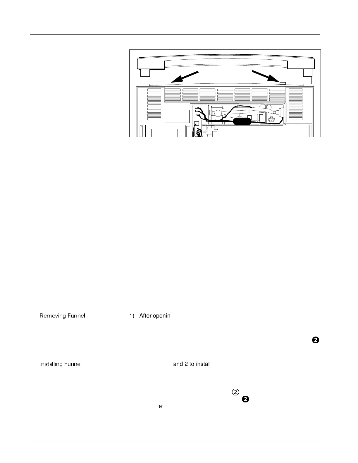
Figure 3-8 Top Release Tabs for Front Bezel Subassembly
4) Return monitor to its proper upright position, with back of monitor
facing you.
5) Insert tip of small screwdriver into each of two release slots on top of
monitor (see Figure 3-8), as you apply a slight tension between front
bezel subassembly and rear housing, to slightly separate top of front
bezel subassembly from rear housing.
Note: It is helpful to lift the handle as shown in Figure 3-8 to access
the release slots.
6) Turn monitor around so that display screen is facing you.
7) Carefully pull Front Bezel Subassembly straight out from rear housing
to unplug interfacing connector on back right-hand side of Front Bezel
PCB from corresponding connector on Main Processing Board, and
separate the two subassemblies.
6 Replacing
Subassemblies in
Rear Housing
The only replaceable components contained in the rear housing, that
require the monitor to be opened, are the Main Processor PCB
Subassembly, the Funnel, and the Rear Housing Subassembly. Other
replaceable components and subassemblies, that do not require that the
monitor be opened, are discussed in Section 4 above.
6.1 Removing/Installing
Funnel
Tabs on the top edge of the funnel located on the top of the heat sink on the
Main Processor PCB Subassembly lock the funnel into the rear housing.
5HPRYLQJ )XQQHO
1) After opening monitor, set rear housing subassembly bottomside down
so that Main Processor PCB Subassembly is facing you.
2) Using small common-blade screwdriver, depress locking tabs near left
and right sides of funnel through slots on top edge of rear housing (
H
in Figure 3-9 on page 50) to release funnel, and slide funnel out of rear
housing.
,QVWDOOLQJ )XQQHO
Reverse steps 1 and 2 to install funnel.
6.2 Main Processor PCB
Subassembly
The Main Processor PCB Subassembly is secured in the rear housing as
follows:
• Tabs on the top edge of the funnel (
@
in Figure 3-9 on page 50) lock
into slots in the top of the rear housing (
H
in Figure 3-9). The back
bottom edge of the funnel restrains the top edge of the heat sink and
holds the subassembly securely in the housing.

 Loading...