SC 7000 and SC 9000XL Patient Monitors Service Manual
ASK-T898-03-7600 Siemens Medical Systems, EM-PCS Danvers 25
7k9kXLTM.c2.CD_ROM.fm/04-99/kaupp
NOT A CONTROLLED DOCUMENT
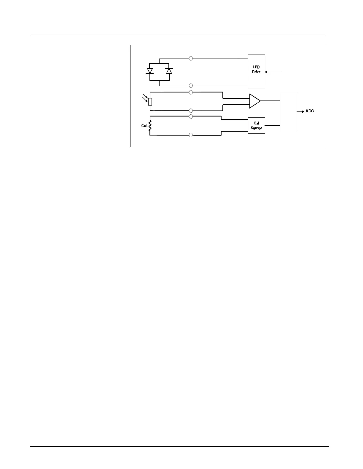
Figure 2-12 SpO
2
Functional Block Diagram
8.3.3 SpO
2
Determination of the concentration of oxygen in the blood depends on the
principle that the absorption of red (R) light depends on the degree of
oxygenation of the blood, whereas the absorption of infrared (IR) radiation
is independent of oxygenation and causes only constant attenuation. Refer
to Figure 2-12. In the SpO
2
sensor, R and IR emitting leds are alternately
pulsed on at a 25% duty cycle. The intensity of light (including ambient)
transmitted through or scattered by the blood is converted to a current by a
photodiode in the sensor. The current that appears when both leds are off
depends mainly on the ambient light. This ambient contribution is later
subtracted to leave only the R or IR signal levels. The large dynamic range
of the light intensities requires constant automatic monitoring and
adjustment.
The intensities of the R and IR sources are independently controlled by two
digital-analog converters attenuating the 2.5V reference.
Attenuated radiation falling on the photodiode in the sensor is converted to
a current which passes through an RF filter balun in the HVPOD and enters
the current-to-voltage converters in the MultiMed front end. The resulting
unipolar stream of pulses is then ac-coupled to a controllable-gain
differential amplifier. The signal is then synchronously demodulated into
Red and IRed signals with ambient light subtracted. Additional gain control,
filtering, and signal offset are provided for each signal prior to A/D
conversion.
The calibration of each sensor is coded into the value of a precision resistor
built into the sensor. The value of this resistor is sensed by forming a
voltage divider. The value of the resistor ratio is read by a separate A/D
input, and out of range values are interpreted as “sensor unplugged.”
Communications The multiplexers and A/D are controlled by the Main Processor via a
Manchester-encoded serial communications channel (Pod Com) optically
coupled to the isolated front end. Most of the digital logic is contained in the
MultiMed FPGA. Outputs from the A/D are Manchester-encoded in the
MultiMed FPGA and fed to the opto-coupled data flow to the Main
Processor.
A power-on monitor resets the FPGA until both ±5V have risen to normal
range. The isolated dc-dc converters are synchronized to the data
acquisition sequence via the Main Processor FPGA. The A/D converter is
automatically calibrated after the power-on reset is cleared.
MUX
DAC
$'&

 Loading...