SC 7000 and SC 9000XL Patient Monitors Service Manual
ASK-T898-03-7600 Siemens Medical Systems, EM-PCS Danvers 13
7k9kXLTM.c2.CD_ROM.fm/04-99/kaupp
NOT A CONTROLLED DOCUMENT
2.11Recorder Interface
The Recorder interface has been designed to connect to an external
recorder via the base unit docking station connector. The recorder interface
provides all of the necessary control, data and power supply signals
required to drive an external recorder. The interface consists of current
limited DC power and a UART with handshake signals. The UART is
implemented in the main processor FPGA to allow for an extended FIFO.
2.12Backlight Control
SC 7000 and SC 9000XL displays require a fluorescent backlight for visibility.
The backlight invertor is located on the front bezel board. Intensity of the light
is controlled by a variable power ac inverter and is based on ambient light
detection as well as operator selection. A 10KHz 6 bit PWM is implemented
in the main processor FPGA, and a filter on the front bezel board converts
this digital signal to an analog voltage to control the backlight intensity.
2.13Serial EEPROMS
Four serial EEPROM devices, which contain the Monitor serial number,
Ethernet address, NBP pneumatic characterization and calibration
constants, and monitor setups, are located on the connector I/O board and
are part of the rear housing. If the main processor board is replaced the
monitor will keep its set ups from these serial EEPROMs.
Two EEPROMs can be written only at the factory, and contain the Monitor
serial number and Ethernet ID address. The other devices are writable by
the main processor and are changed during service menu setups. These
devices are used for the monitor as well as network setups, device
compatibility, and software feature locks.
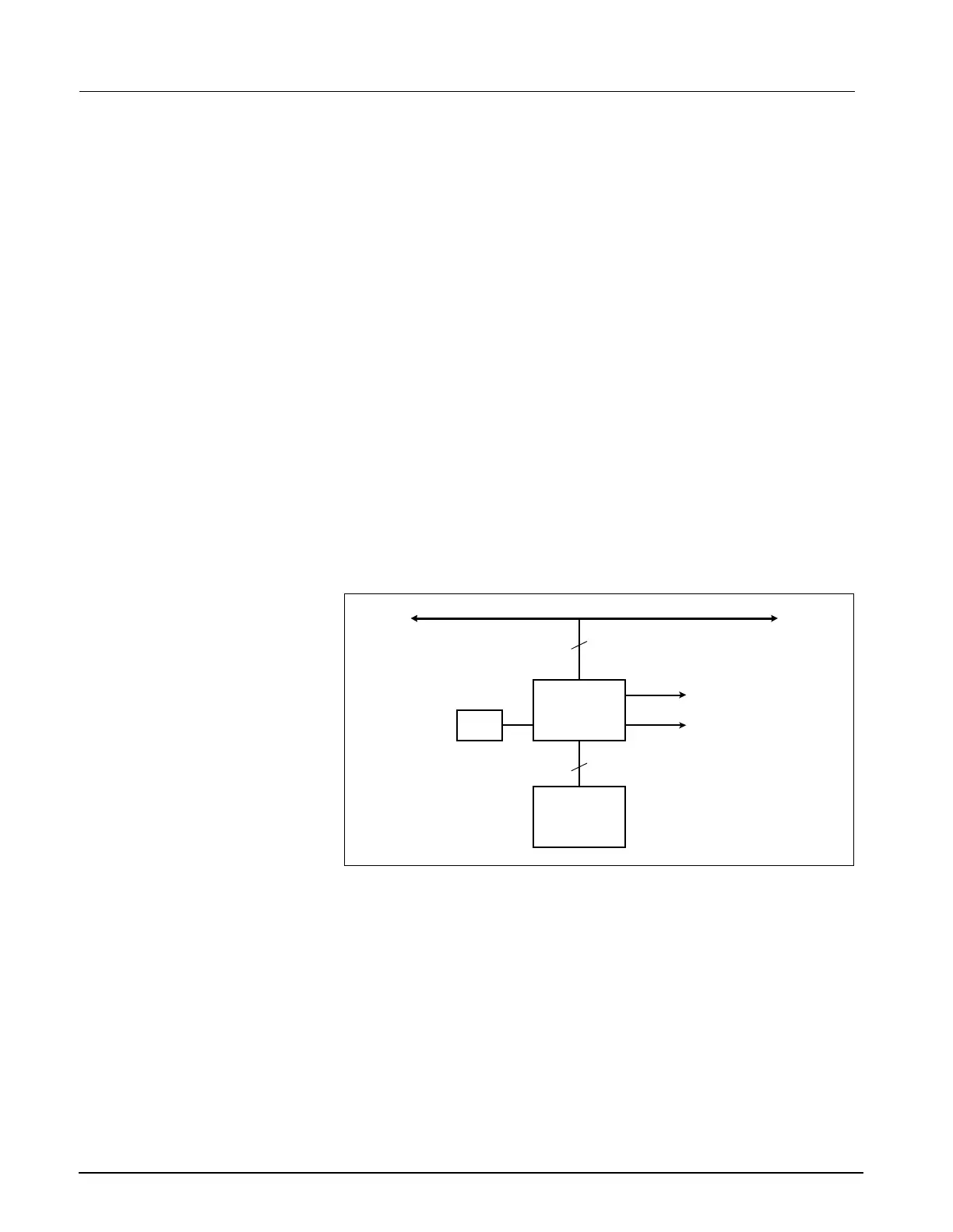
Figure 2-4 Graphics Subsystem
3Graphics Subsystem
3.1 Overview
The Graphics Subsystem is based on a commercial VGA controller (see
Figure 2-4), and drives both a CRT and LCD display from a local memory
used to refresh the screen. It uses a special video crystal which enables it
to synchronize to most video standards. The graphics chip is capable of
running resolutions such as 800 x 600, when these displays are added to
the monitor. The standard resolution is set to 640 X 480.
3.2 Functional Description
The VGA subsystem is designed to optimize the Bitblit operation, which
allows for quick updates of the screen. This is accomplished by writing
images to non-viewable areas of video memory before they are needed and
copying them to the screen on demand. The copy function is performed by
the VGA controller.
VGA Controller
CRT Interface
LCD Interface
MAIN BUS
DRAM Video
Buffer
Video
Crystal
32
32

 Loading...