SC 7000 and SC 9000XL Patient Monitors Service Manual
ASK-T898-03-7600 Siemens Medical Systems, EM-PCS Danvers 53
7k9kXLSM.c3.CD_ROM.fm/04-99/kaupp NOT A CONTROLLED DOCUMENT
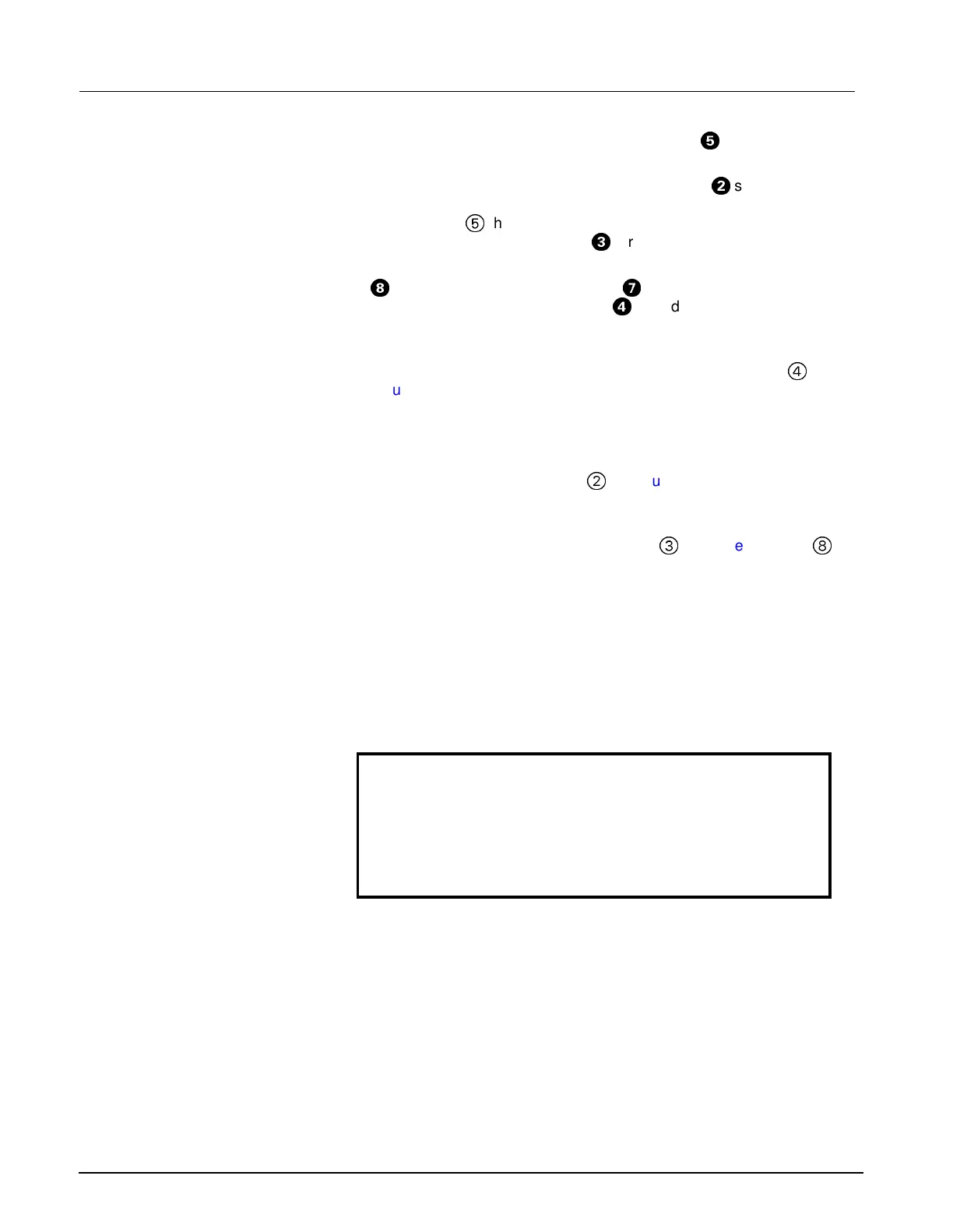
6) Unplug optical encoder ribbon cable connector (
<
in Figure 3-10 on
page 51 and Figure 3-12 on page 52) from Front Bezel PCB.
7) Refer to Figure 3-10 or Figure 3-12. Unscrew nut
H
securing optical
encoder shaft in position in front bezel, and remove optical encoder
subassembly
5
through back of panel. Save nut, and lock washer /
positioning washer combination
9
for use in reassembly.
8) Refer to Figure 3-10. Unplug membrane switch ribbon cable connector
@
and display backlight connectors
?
from Front Bezel PCB, and
display screenflex cable connector
;
from display screen
subassembly PC board.
9) Slide small screwdriver under tab near bottom on right hand side of
display subassembly, and carefully lift display subassembly (
4
in
Figure 3-10) out of front bezel frame. Set subassembly aside on a
clean flat surface for use in reassembly.
Note: Be very careful that no dust or other foreign matter gets on the
front bezel lens or on the display screen surface.
10) Remove and save two screws (
@
in Figure 3-11 on page 51)
securing Front Bezel PC Board interface connector to mounting tabs
on front bezel frame.
11) Remove and save two remaining screws (
3
in Figure 3-11 and
8
in
Figure 3-10) securing Front Bezel PC Board to front bezel frame.
12) Lift bottom right hand side of Front Bezel PC Board off of front bezel
frame, and slide board out from under interface connector mounting
tabs to remove board.
7.1.2 Installing Front Bezel PC
Board
1) With optical encoder and display screen subassemblies removed, and
front bezel subassembly laying face down on a smooth clean surface,
bottom facing you, slide Front Bezel PC Board into position on
mounting posts on front bezel frame, with interface connector housing
under front bezel frame connector mounting tabs.
Caution
The flex cable and connector on the right-hand side of the Front
Bezel PC Board can be easily damaged. Be particularly careful
when positioning the board in the front bezel subassembly or
reinstalling the display screen subassembly in step 5 below.
2) Install screws removed in step 10 above into interface connector
housing but do not tighten until step 4 below.
3) Install screws removed in step 11 above, and tighten to secure Front
Bezel PC Board to front bezel frame.
4) Tighten screws installed in step 2 to secure interface connector
housing to front bezel frame.
5) Locate display subassembly in front bezel frame and press to seat
subassembly into position.
Note: Be very careful that no dust, finger prints, or other foreign
matter is on the front bezel lens or on the display screen surface.

 Loading...