Service Manual SC 7000 and SC 9000XL Patient Monitors
70 Siemens Medical Systems, EM-PCS, Danvers ASK-T898-03-7600
NOT A CONTROLLED DOCUMENT
7k9kXLSM.c4.CD_ROM.fm/04-99/kaupp
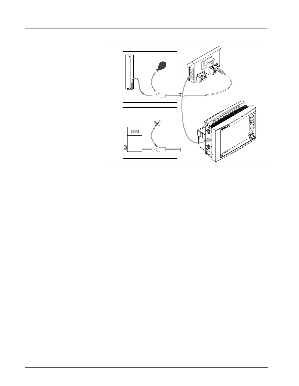
Figure 4-3 IBP Functional Verification Test Setup for HEMO2/4 PODs
If verifying proper IVP functioning of only the Monitor, do sections 13.1.1
and 13.1.2, and then go on to section 13.2. If functionally verifying the
HEMO POD also complete sections 13.1.3, 13.1.4, and 13.1.5.
13.1.1 IBP Test setup 1) With MultiMed cable and all other patient inputs unplugged from
monitor, power-cycle monitor. Select NO to clear display.
2) Plug cable from HEMO POD IBP SC 9000 output into Aux./Hemo3
input on SC 7000 or SC 9000XL monitor.
13.1.2 HEMO2/4 POD Channel A 3) With
MAIN
screen displayed, connect BP output from simulator to first
input, channel A, on HEMO POD adapter.
4) Set IBP simulator for a static pressure = 0 mmHg.
Note: “Zero Required” message, identified by same pressure label is
shown in LCD window for channel A on front of HEMO POD appears
on display.
Monitor Zero Function 5) Press Zero All key on HEMO POD.
6) Verify that a “Zero Accepted” message that changes to “Static
Pressure”, both identified by the same pressure label, appear in the
message field.
7) Select a pulsatile pressure on patient simulator.
8) Assure that Cal Factor and Manometer Cal are set to 100.
9) Verify that pressure reading on monitor is in agreement with values
generated by pressure signal from simulator.
10) If monitor is an SC 9000XL, plug cable from HEMO POD IBP SC 9000
output into Aux./Hemo2 input and repeat steps 3 through 9. Otherwise,
continue.
11) If functionally verifying only the SC 7000 or SC 9000XL, omit the
remaining steps in this section and go to Section 13.2. If also
functionally verifying HEMO POD, go on to step 12.
290
270
250
230
210
190
170
150
130
110
90
70
5
300
280
260
240
220
200
180
160
140
120
100
80
60
40
20
0
Pressure
Transducer
Tester
Inflation
Bulb
Manometer
Stopcock
(Closed)

 Loading...