4. Start the device.
To commission the analyzer modules, follow the procedure described in the section
"Commissioning (Page121)".
5. Enter the user-specic parameters of the basic device again.
If the parameters have been saved on a PC using SIMATIC PDM, download the parameters to
the device.
11.7 Replacing the processing module
Procedure
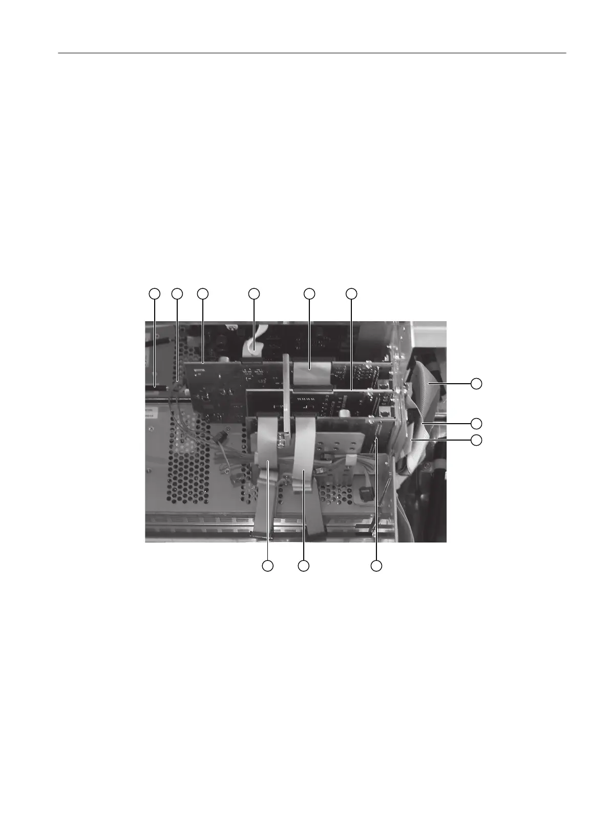
① Power cable ⑦ Connecting cable TB - PU
② 12-pin ribbon cable to the AM (CAN bus) ⑧ Connecting cable TB - OM 1.1
③ Processing unit (PU) ⑨ Connecting cable TB - OM 2.1
④ 26-pin ribbon cable to display ⑩ Option module OM 2.1
⑤ Connecting cable OM 1.1 - PU ⑪ 26-pin ribbon cable to the AM1
⑥ Option module OM 1.1 ⑫ 26-pin ribbon cable to AM2
Figure11-3 Cabling using OM 1.1 and OM 2.1 as an example
Maintenance and servicing
11.7Replacing the processing module
Wall-mounted device
Operating Instructions, 07/2023, A5E31930403-AB 149
 Loading...


