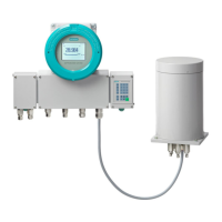
Table 5-1 Mounting position of the sample gas restrictor: OXYMAT7
Operating
mode
Sample gas restrictor/clamping screw
Operation with one
OXYMAT7
Operation with two OXY‐
MAT7 in series
Operation with two OXY‐
MAT7 in parallel
Pressure op‐
eration
Install a sample gas restric‐
tor in front of the sample
gas inlet.
Install a sample gas restric‐
tor in front of the sample
gas inlet into which the sam‐
ple gas is introduced rst.
In addition replace the sam‐
ple gas restrictor in the inlet
of the rear, second module
with a clamping screw.
Install a sample gas restric‐
tor in front of each sample
gas inlet.
Suction oper‐
ation
Install a sample gas restric‐
tor in the sample gas outlet
Install a sample gas restric‐
tor in the sample gas outlet
from which the sample gas
is rst sucked out:
In addition replace the sam‐
ple gas restrictor in the inlet
of the rear, second module
with a clamping screw.
Install a sample gas restric‐
tor at each sample gas out‐
let
5.4.4 Operation with at least one ULTRAMAT 7
Table 5-2 Mounting position for the sample gas restrictor: ULTRAMAT 7
Operating mode Sample gas restrictor/clamping screw
Operation with one or two ULTRAMAT7
Pressure operation/Suction operation No sample gas restrictor/clamping screw required Subse‐
quent upgrading or retrotting is not possible and not re‐
quired.
There are no particular mounting restrictions.
5.4.5 Operation with at least one CALOMAT 7
Table 5-3 Mounting position for the sample gas restrictor: CALOMAT 7
Operating mode Clamping screw
Operation with one or two CALOMAT7
Pressure operation/Suction operation Pre-assembled clamping screws. No retrotting or disman‐
tling required.
Combined operation
5.4Application planning
Wall-mounted device
Operating Instructions, 07/2023, A5E31930403-AB 49

 Loading...


