7.11.2 Installing option modules
Preparing for installation
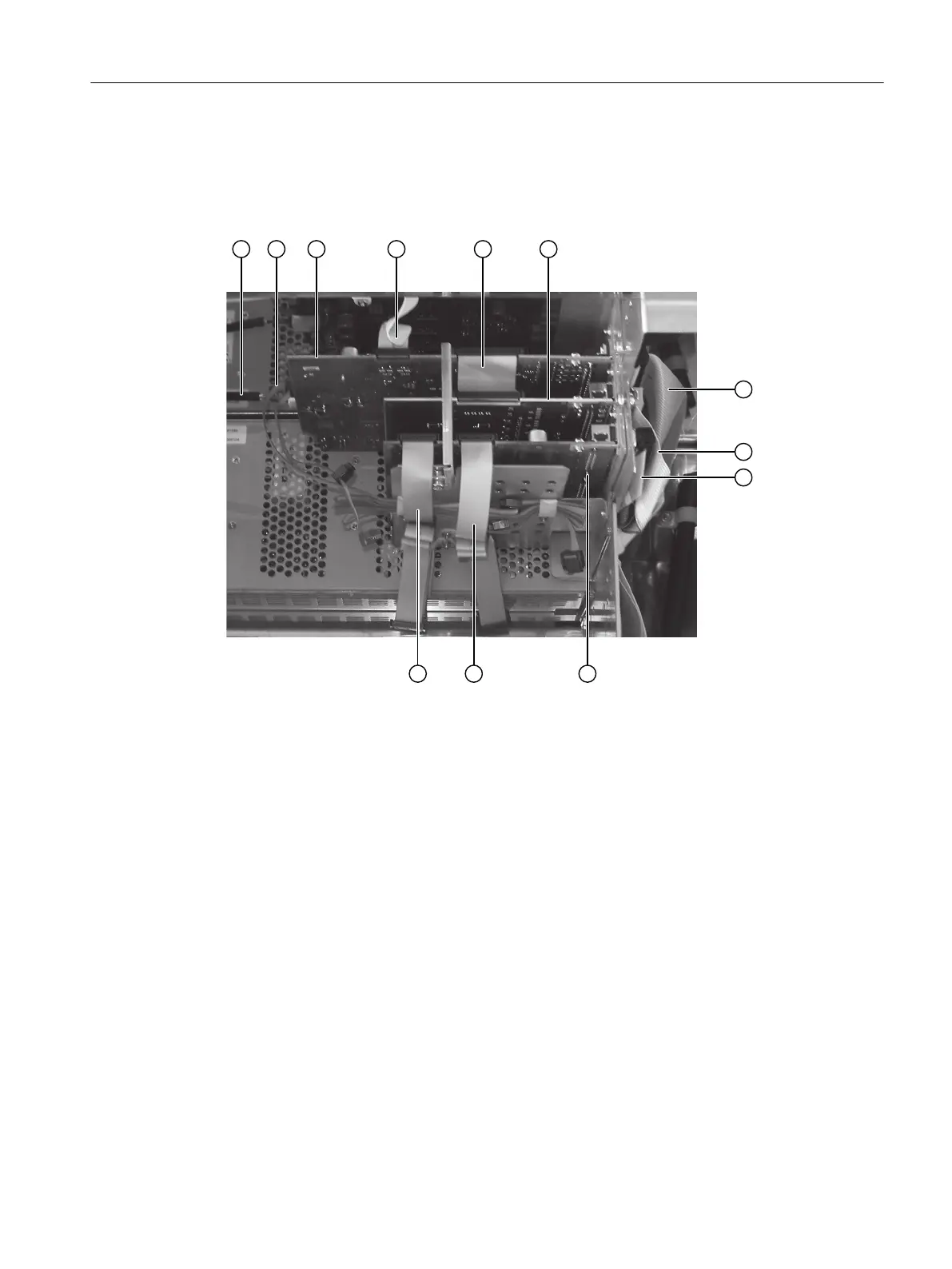
① Power cable ⑦ Connecting cable TB - PU
② 12-pin ribbon cable to the AM (CAN bus) ⑧ Connecting cable TB - OM 1.1
③ Processing unit (PU) ⑨ Connecting cable TB - OM 2.1
④ 26-pin ribbon cable to display ⑩ Option module OM 2.1
⑤ Connecting cable OM 1.1 - PU ⑪ 26-pin ribbon cable to the AM1
⑥ Option module OM 1.1 ⑫ 26-pin ribbon cable to AM2
Figure7-13 Cabling using OM 1.1 and OM 2.1 as an example
1. Isolate the device from power.
2. Loosen the six screws and open the door.
3. Loosen the three screws and remove the shield plate for signal cables (see the gure below).
4. Pull out the connectors for the following cables depending on the installation situation:
– Power cable ①
– 26-pin ribbon cable to display ④
– 12-pin ribbon cable to analyzer modules AM and option module OM2.2 ②
– 26-pin ribbon cable to the analyzer modules ⑪⑫
– Connecting cable to the terminal block (TB) ⑦⑧⑨
– If applicable, Ethernet-cable on the processing unit.
Installing / removing and connecting analyzer and option modules
7.11Installing option modules
Wall-mounted device
Operating Instructions, 07/2023, A5E31930403-AB 83
 Loading...


