7.2 Wall housing tool
The following tools are required for the mounting/removal of the analyzer module in the wall
enclosure:
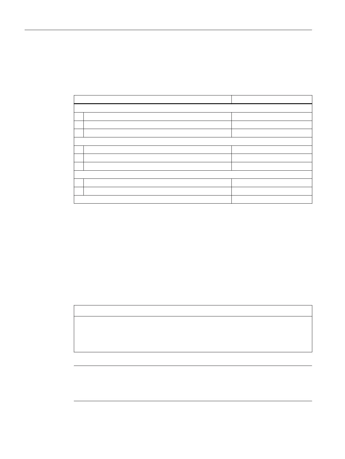
Table 7-1 Wall housing tool
Designation Quantity
Screwdriver
Torx T25 1
Torx T20 1
Torx T10 1
Hexagon socket wrench
SW5 1
SW7 1
SW8 1
Open-ended wrench
SW22 1
SW27 1
Torque wrench 0.3to5.0Nm 1
7.3 Cables
Overview
Each analyzer module has a cable set. The CAN BUS cable which interconnects all components
always has the full range of connections.
The enclosure contains plastic retainers that are used to fasten the cables. The at cables and
ribbon cables are laid separate from each other in the enclosure and fastened with cable ties
to plastic retainers.
NOTICE
Cable damage
Cables can be damaged by friction or other mechanical inuences.
• Lay the cables carefully again after installation or when you replace an analyzer module and
secure them in the housing at the plastic holders.
Note
Order spare parts separately
When you install option modules into the basic device later, order the associated sets of cables
separately.
Installing / removing and connecting analyzer and option modules
7.3Cables
Wall-mounted device
66 Operating Instructions, 07/2023, A5E31930403-AB
 Loading...


