The door ① is tted with a display ③ and a keyboard ④ and is locked via mounting holes
② with six screws.
The device provides space for the installation of two unheated analyzer modules AM1 ⑭ and
AM2 ⑬ and two option modules. Due to their size, only single high-temperature modules
can be installed since they use both slots AM1 ⑭ and AM2 ⑬.
You can nd more information on the slots of the option modules in the section "Mounting
locations of option modules (Page81)".
The interior rear wall of the housing contains a power supply unit ⑦ and before it a
processing unit ⑤. A shield plate ⑥ for signal cables is fastened in the housing on the right.
At the underside of the device there are cable glands for the power supply cord ⑫, the signal
cable ⑧ and the Ethernet ⑨ as well as a connection to the equipotential bonding ⑪ and
two optional connections for purge gas: Purge gas inlet ⑮ and purge gas outlet ⑩.
4.3 Device/module identication
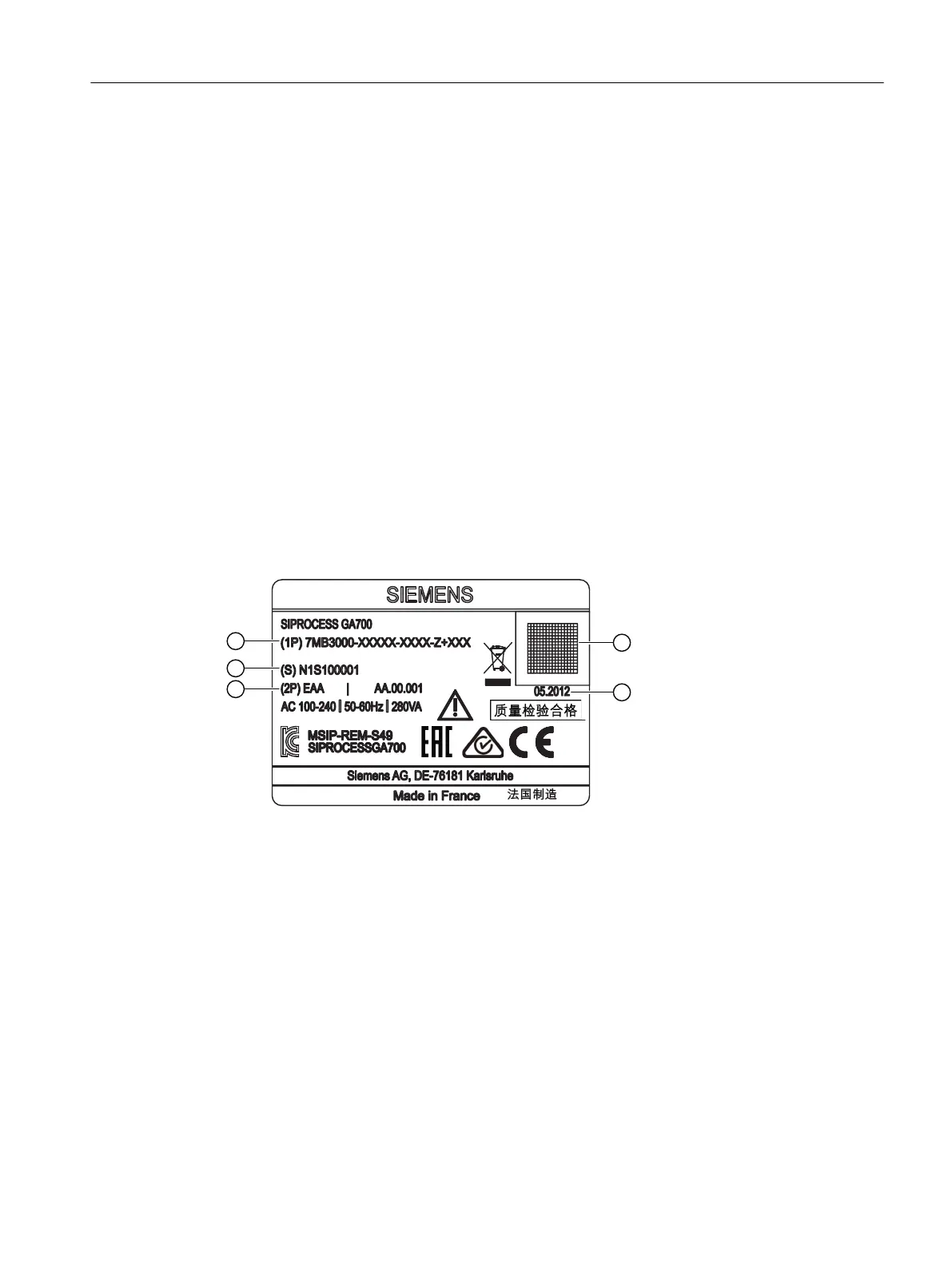
4.3.1 Nameplate layout
① Article number ④ DataMatrix Code ECC 200
② Serial number ⑤ Date of manufacture
③ Revision status
Figure4-2 Nameplate
The nameplate with the article number and other important information is located on top of
the enclosure exterior.
Description
4.3Device/module identication
Wall-mounted device
Operating Instructions, 07/2023, A5E31930403-AB 23
 Loading...


