3. Remove the equipotential bonding cable ⑥ from the blank plate at slot 1.
Note: The cable for equipotential bonding ⑥ is no longer required after the analyzer
module ④ is installed. See section "Installing analyzer modules, standard version (Page 68)".
4. Check the at seal ⑤ for damage.
Replace the at seal if it is damaged or porous.
5. Swivel the analyzer module forward and insert it into the wall housing ①.
6. Secure the analyzer module ④ in slot 1 as follows:
– Use eight screws on the base of the housing ③ with a torque of 0.8Nm.
– Use two screws on the rear panel with a torque of 2.5Nm.
7. Connect the gas lines, see section "Device with one ULTRAMAT 7 analyzer module, high-
temperature version (Page103)".
7.7 Connecting analyzer modules
7.7.1 Wiring OXYMAT 7
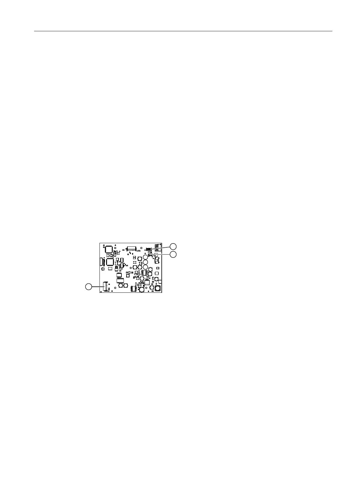
Overview
① CAN interface, 12-pin ribbon cable ③ Interface, 26-pin ribbon cable to option mod‐
ule OM 2.1/2.2
② Connector for cable from power supply unit
Figure7-6 Analyzer module printed circuit board, interfaces OXYMAT 7
Procedure
1. When an option module OM 2.1 or OM 2.2 is installed:
Connect the option module to the interface ③ of the analyzer module printed circuit board
(AM-FBG) using the existing 26-pin ribbon cable.
2. Connect the processing unit (PU) to the CAN interface ① on the analyzer module printed
circuit board (AM-FBG) using the existing 12-pin ribbon cable.
3. Ensure that power is provided to the analyzer module printed circuit board from the power
supply unit ② via the power cable, see Connecting the power supply (Page113).
4. Connect the gas connections, see OXYMAT 7 (Page95).
Installing / removing and connecting analyzer and option modules
7.7Connecting analyzer modules
Wall-mounted device
Operating Instructions, 07/2023, A5E31930403-AB 73
 Loading...


