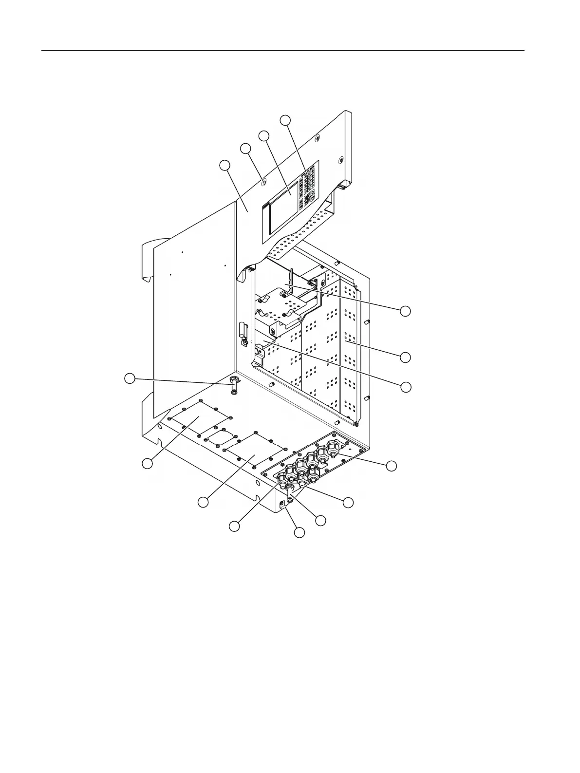
4.2 Structure of the wall enclosure
① Door ⑨ Ethernet cable gland (only metal version)
② Fastening hole for door screw (6 units) ⑩ Purging gas connection outlet (optional)
③ Display ⑪ Equipotential bonding connection
④ Keyboard ⑫ Cable gland power supply cord
⑤ Processing unit ⑬ Slot of analyzer module 2 (AM2)
⑥ Shielding plate ⑭ Slot of analyzer module 1 (AM1)
⑦ Power supply unit ⑮ Purging gas connection inlet (optional)
⑧ Cable gland signal cable
Figure4-1 Wall housing design
The device is attached to the wall with four screws, see section "Installing the wall-mounted
device (Page63)".
Description
4.2Structure of the wall enclosure
Wall-mounted device
22 Operating Instructions, 07/2023, A5E31930403-AB
 Loading...


