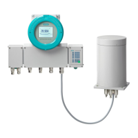
Procedure
1. Isolate the wall-mounted device from power.
2. Loosen the clamping ring connections at the gas inlets and outlets.
3. Loosen the six screws ② and open the door of the wall housing.
4. Remove the following cables:
– Power cable to the analyzer module printed circuit board and power supply unit
– 12-pin ribbon cable (CAN) to the analyzer module printed circuit board and the
processing unit
– If applicable, 26-pin ribbon cable to the analyzer module printed circuit board or the
analog output adapter card and the option module OM 2.1 or OM 2.2
5. Loosen the eight Torx screws ③ on the base of the housing and the two Torx screws on the
rear wall.
6. Swivel the analyzer module ④ forward and remove it from the wall enclosure.
7. If you are not installing and connecting a new analyzer module:
Fasten the blank plate over the slot using the eight Torx screws ③ with a torque of 0.8 Nm.
8. Close the door of the housing with the six screws ②.
Tighten the screws ② on the door with a torque of 3.5Nm.
7.11 Installing option modules
Note
Enable analog and digital outputs
If you subsequently install an option module 2.1, you must enable the analog and digital outputs
using SIMATIC PDM after restarting:
1. Establish a connection between SIMATIC PDM and the analyzer.
You may have to log on at the Expert level.
2. Navigate to: Parameter group overview > Properties > Device
3. For the "Option module 2.1" parameter, set the value "Yes".
4. Transfer the modied parameter assignment to the device.
7.11.1 Mounting locations of option modules
Features
You can nd information on option module features with inputs and outputs in the section
"Technical specications (Page161)".
Installing / removing and connecting analyzer and option modules
7.11Installing option modules
Wall-mounted device
Operating Instructions, 07/2023, A5E31930403-AB 81

 Loading...


