Service Parts Disassembly 8-79
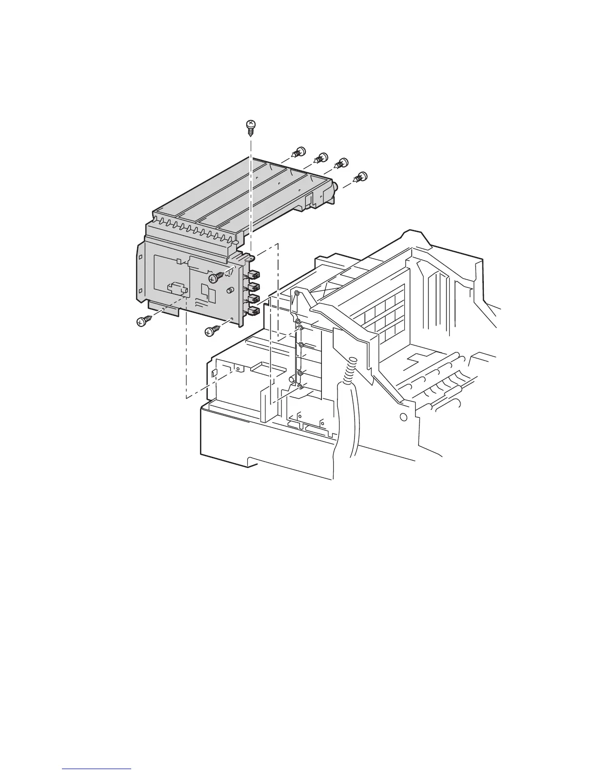
13. Remove the 8 screws securing the Toner Cartridge Holder Unit and carefully
remove the unit to the left. Flex the Dispenser Plate slightly during removal to
clear the locator pin and the clearance notch at the front.
Note
The 4 screws on the right side of the printer are below the toner motors.
Replacement Notes
1. Replace in reverse order. Reconnect the ground wire using the front lower screw
on the left side.
Note
An “Install or Reseat Imaging Unit” error can occur if the Gear and Rack V
are not properly aligned. With Door C open, push the Rack V as far up as it
can go, then replace the gear.
6250-216
 Loading...