8-110 Phaser 6250 Color Laser Printer Service Manual
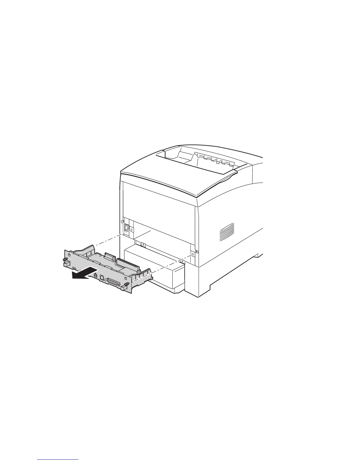
Image Processor Board (PL12.1.4)
Caution
Observe proper ESD procedures (page 8-3) when removing any circuit
board from the printer.
1. Turn the printer power off.
2. Disconnect any cables attached to the Image Processor board.
3. Loosen the 2 thumb screws securing the Image Processor board to the printer.
4. Holding both knobs on the Image Processor board, pull the board straight out
from the printer to remove.
Replacing the Board
The following items MUST be moved from the original Image Processor Board to the
new board. See "Image Processor Board' on page 9-32 for the exact locations of each
component.
■ Memory
■ Hard Drive (if installed)
■ Configuration Upgrade Chip (‘i’ Button)
■ NVRAM
Print a Configuration Page after the new board is installed to ensure the customers
configuration is correct.
6250-251
 Loading...