2-18 Phaser 6250 Color Laser Printer Service Manual
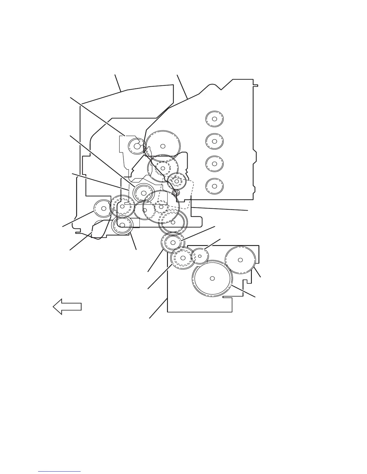
Gear Layout - Print Engine and Tray 1
The drawing below shows the location of the various components specified in the
Transmission Route Block Diagram on the preceding page.
1. Retard Housing 9. Turn Clutch Assembly
2. Tray 1 Gear 10. Gear Idler Feed
3. Registration Chute Assembly 11. Gear Feed 1
4. Registration Clutch 12. Gear Feed H1
5. Transfer Roller 13. Paper Pick Assembly (Tray)
6. Chute Assembly Out 14. Gear Idler
7. Imaging Unit 15. Gear Idler In
8. Main Drive Assembly 16. Turn Clutch
FRONT
6250-052
1
2
3
4
5
6
7
8
9
10
15
16
14
13
12
11
 Loading...