8-104 Phaser 6250 Color Laser Printer Service Manual
11. Disconnect P/J 2361 (yellow wires) going to the Temperature/Humidity Sensor.
12. Disconnect P/J 144 (yellow wires) from the EEPROM Board (PL 10.1.14).
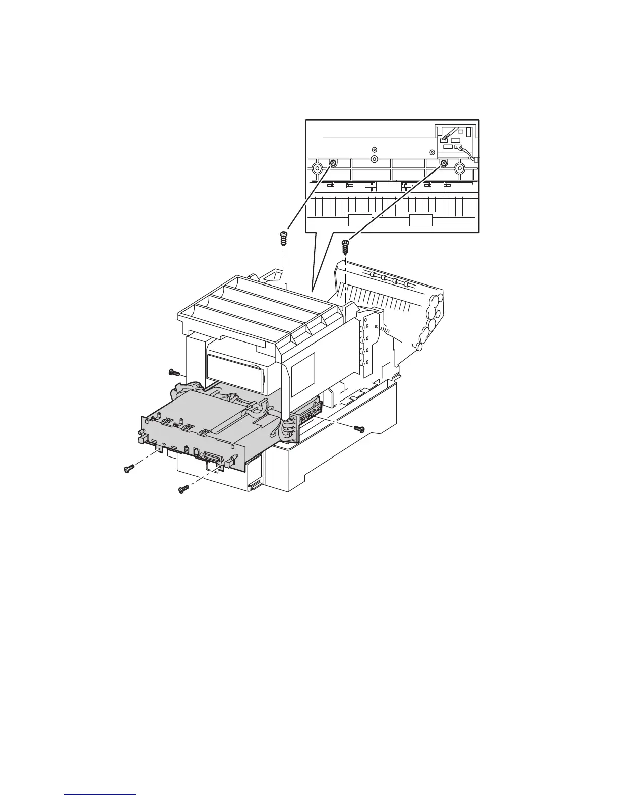
13. At the front of the card cage, remove the two screws from the metal of the card
cage, not the two screws secured in the plastic (see the following figure).
14. Remove the two mounting screws for the Rear Fan and move it out of the way.
Caution
Note the fan orientation for reassembly, the label should face out towards the
rear of the printer.
Note
A total of 6 screws including the 2 removed in Step 13) secure the Card
Cage. The remaining 4 are located as follows: 2 on the rear under the card
cage, 1 on the left side below the Sub-HVPS board, and 1 on the right at the
rear of the LVPS.
15. Remove the 4 screws still securing the Card Cage to the printer and remove the
card cage.
6250-235
 Loading...