2-10 Phaser 6250 Color Laser Printer Service Manual
+n of this control is outlined below:
1. With no toner on the Transfer Roller, the output value of Sensor, CTD (ADC) is
measured to determine the threshold value.
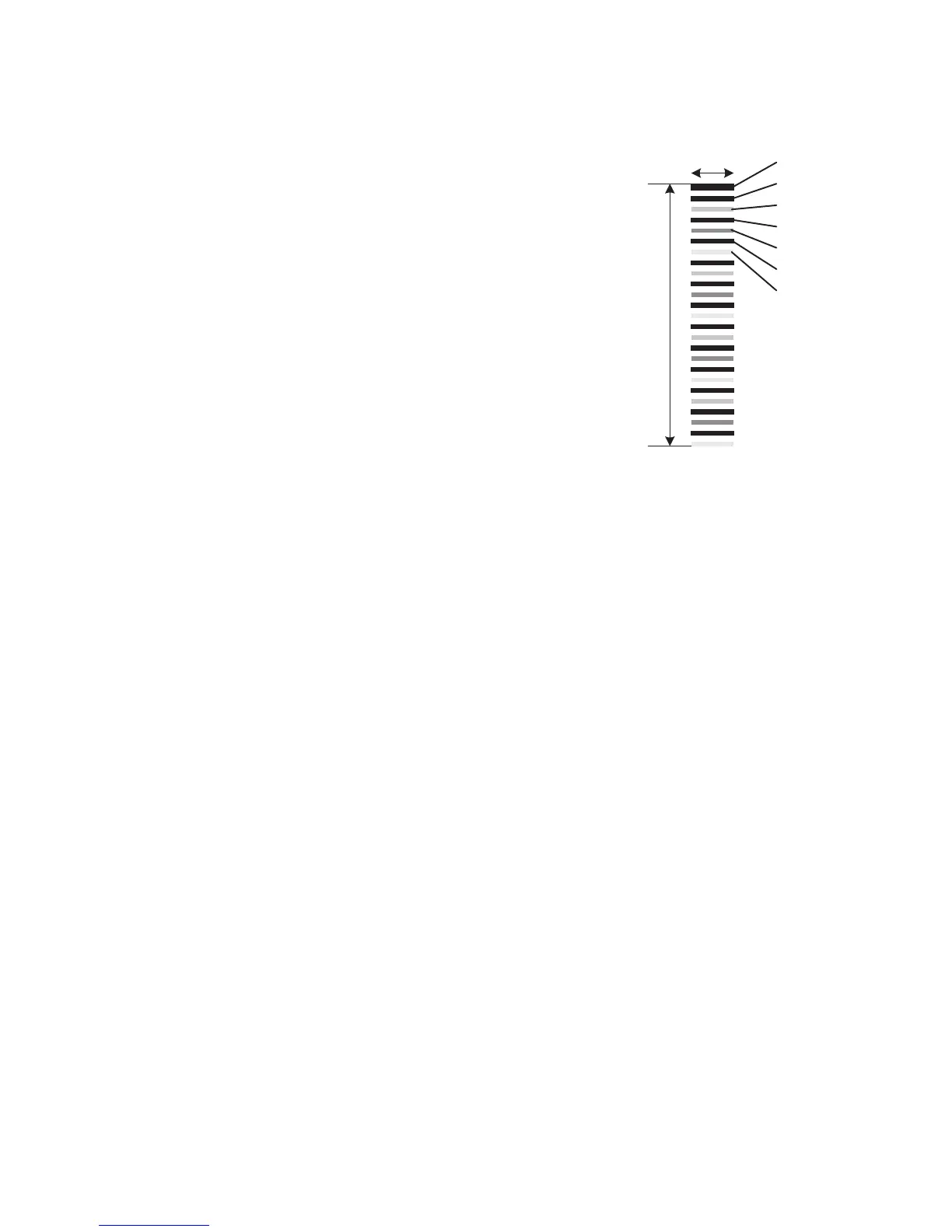
2. Patches for color registration control are
generated on the Transfer Roller. These
patches are composed of 10mm lines of
each toner color in the following order: K,
C, K, M, K, and Y with each color
dispensed in the amount of four dispense
counts. The string of patches is led by a
black trigger patch that is larger than the
registration patches.
3. The density of patches generated by the
CTD (ADC) sensor is measured.
4. The amount of registration shift is
calculated from the threshold value
determined in Step 1 and the patch density
measured in Step 3.
5. The laser write timing is changed to
compensate for the amount of registration
shift.
10mm
About one turn of BTR
K
K
C
K
M
K
Y
6250-068
 Loading...