ENGINE (YP125R)
3-8
8. Install:
• V-belt case air filter element
• V-belt case air duct
• V-belt case cover
9. Install:
• Storage box
Refer to “GENERAL CHASSIS” on page 4-1.
EAS37P1089
ADJUSTING THE EXHAUST GAS VOLUME
IP
Be sure to set the CO density level to standard,
and then adjust the exhaust gas volume.
1. Remove:
• Upper panel
Refer to “GENERAL CHASSIS” on page 4-1.
2. Set the main switch to “OFF”.
3. Disconnect:
• Self-diagnosis signal coupler
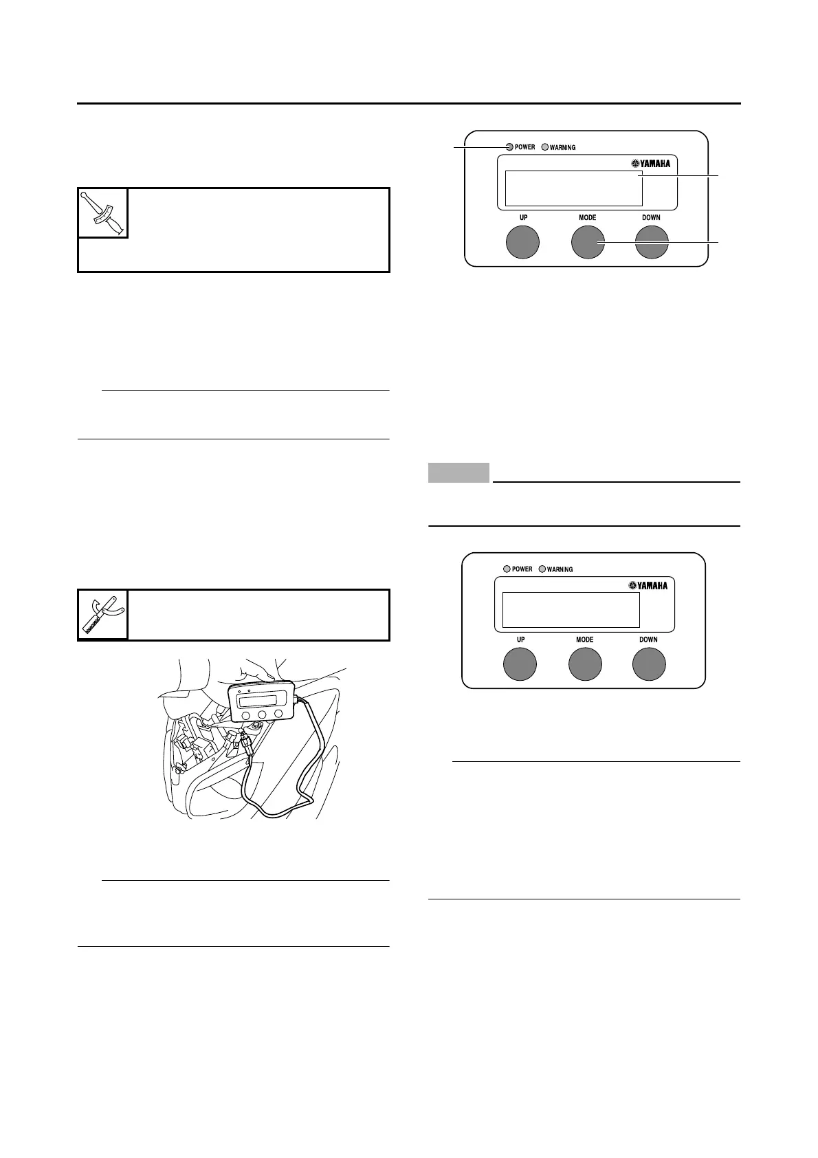
4. Connect:
• FI diagnostic tool “1”
5. While pressing the “MODE” button “1”, set
the main switch to “ON”.
IP
•“DIAG” appears on the LCD “2” of the FI diag-
nostic tool.
•“POWER” LED (Green) “3” comes on.
6. Press the “UP” button to select the CO adjust-
ment mode “CO” or the diagnostic mode “DI-
AG”.
7. After selecting “CO”, press the “MODE” but-
ton.
8. Check that “C1” appears on the LCD of the FI
diagnostic tool, and then press the “MODE”
button.
9. Start the engine.
NOTICE
ECA37P1042
Perform the adjustment after the battery has
been sufficiently charged.
10.Change the CO adjustment volume by press-
ing the “UP” and “DOWN” buttons.
IP
The CO adjustment volume and engine idling
speed appears on the LCD of the FI diagnostic
tool.
• To decrease the CO adjustment volume, press
the “DOWN” button.
• To increase the CO adjustment volume, press
the “UP” button.
11.Release the “DOWN” and “UP” buttons to ex-
ecute the selection.
12.Set the main switch to “OFF” to cancel the
mode.
13.Disconnect:
• FI diagnostic tool
14.Connect:
• Self-diagnosis signal coupler
T
R
.
.
V-belt case air duct bolt
7 Nm (0.7 m·kgf, 5.1 ft·lbf)
V-belt case cover bolt
7 Nm (0.7 m·kgf, 5.1 ft·lbf)
FI diagnostic tool
90890-03182
1
FI Diagnostic Tool
DIAG
1
2
3
FI Diagnostic Tool
1700rpm
C1
: -10
 Loading...