THROTTLE BODY
7-5
EAS26970
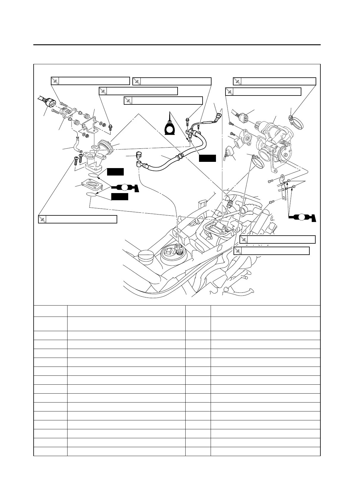
THROTTLE BODY
Removing the throttle body (YP125R)
Order Job/Parts to remove Q’ty Remarks
Storage box/Footrest board
Refer to “GENERAL CHASSIS” on page
4-1.
1 Intake air pressure sensor hose 1
2 Intake air pressure sensor coupler 1 Disconnect.
3 Intake air pressure sensor 1
4 Intake air pressure sensor bracket 1
5 ISC (idle speed control) unit coupler 1 Disconnect.
6 Throttle position sensor coupler 1 Disconnect.
7 Throttle position sensor 1
8 Throttle cable 2 Disconnect.
9 Air filter case joint clamp screw 1 Loosen.
10 Throttle body joint clamp screw 1 Loosen.
11 Throttle body 1
12 Fuel injector coupler 1 Disconnect.
13 Fuel hose connector cover 1
14 Fuel injector assembly 1
10 Nm (1.0 m
•
kgf, 7.2 ft
•
Ibf)
T
.R.
10 Nm (1.0 m
•
kgf, 7.2 ft
•
Ibf)
T
.R.
10 Nm (1.0 m
•
kgf, 7.2 ft
•
Ibf)
T
.R.
2 Nm (0.2 m
•
kgf, 1.4 ft
•
Ibf)
T
.R.
12 Nm (1.2 m
•
kgf, 8.7 ft
•
Ibf)
T
.R.
1.5 Nm (0.15 m
•
kgf, 1.1 ft
•
Ibf)
T
.R.
3 Nm (0.3 m
•
kgf, 2.2 ft
•
Ibf)
T
.R.
5 Nm (0.5 m
•
kgf, 3.6 ft
•
Ibf)
T
.R.
10 Nm (1.0 m
•
kgf, 7.2 ft
•
Ibf)
T
.R.
New
2
New
New
LS
3
1
4
16
15
13
12
14
5
11
7
6
10
9
8
LS
E
 Loading...